System and method for locking retention of valve components

a technology of locking retention and valve components, which is applied in the field of fluid control valves, can solve the problems of increased space use, increased malfunction opportunities among multiple components, and increased cost and weigh

Active Publication Date: 2014-01-28
COLLINS ENGINE NOZZLES INC
View PDF13 Cites 9 Cited by
  • Summary
  • Abstract
  • Description
  • Claims
  • Application Information

AI Technical Summary

Benefits of technology

[0012]It is also contemplated that in certain embodiments the hold-down sleeve includes an inward protruding cleat defined on a downstream portion thereof. The downstream end portion of the valve body can include a circumferential groove with the cleat of the hold-down sleeve engaged with the circumferential groove of the valve body. A housing can be engaged outboard of the hold-down sleeve, the housing being configured to maintain engagement of the cleat of the hold-down sleeve in the circumferential groove of the valve body by preventing movement of the cleat radially outward from the circumferential groove. The stop structure of the hold-down sleeve can engage the main spring guide and can compress the main spring to maintain the predetermined minimum clearance between the main spring guide and the valve member of the valve body with the valve body in the closed condition.

Problems solved by technology

However, the use of two separate valve assemblies results in increased cost and weight, increased use of space and increased opportunities for malfunctions to occur among the multiple components that are required.
Typical valves of this type have relied on combinations of separate metering valves and check valves, resulting in relatively large part counts and weights.
Depending on the design and the joining methods used, it can be difficult to achieve a high degree of precision during assembly of previously known multi-port valves.
Imprecise assembly can result in significant deviations between actual valve performance and desired valve performance.
For example, if valve parts are welded or brazed during assembly, thermal expansion or other distortions arising during the welding process can render precision features designed into the valve assembly inoperative.

Method used


Image

  • System and method for locking retention of valve components
  • System and method for locking retention of valve components
  • System and method for locking retention of valve components

Examples


Embodiment Construction

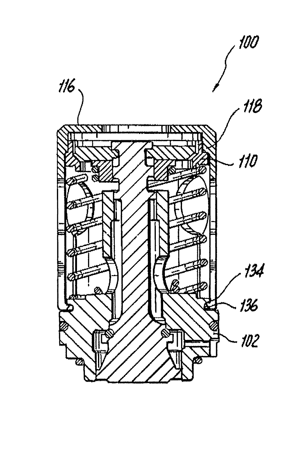
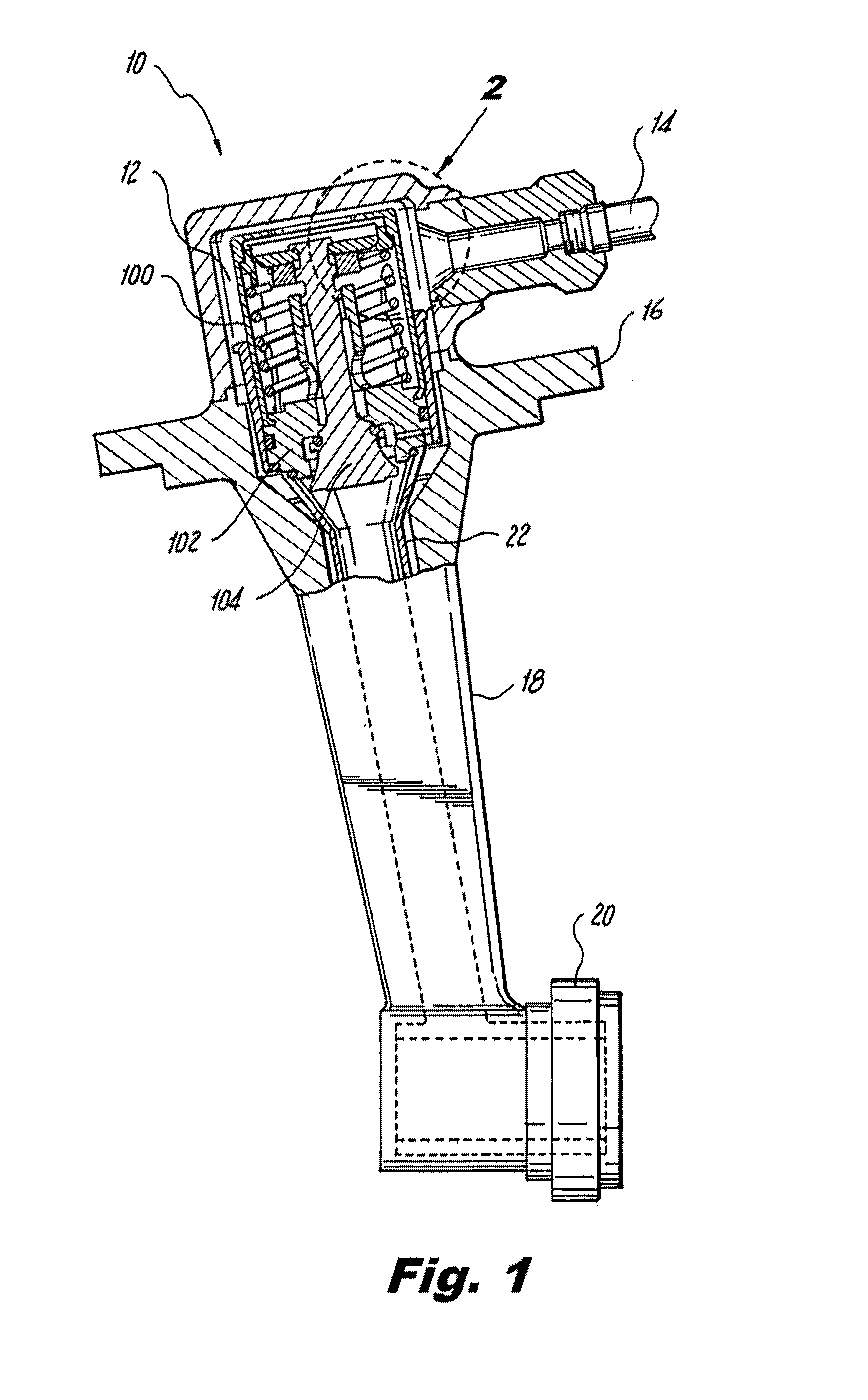
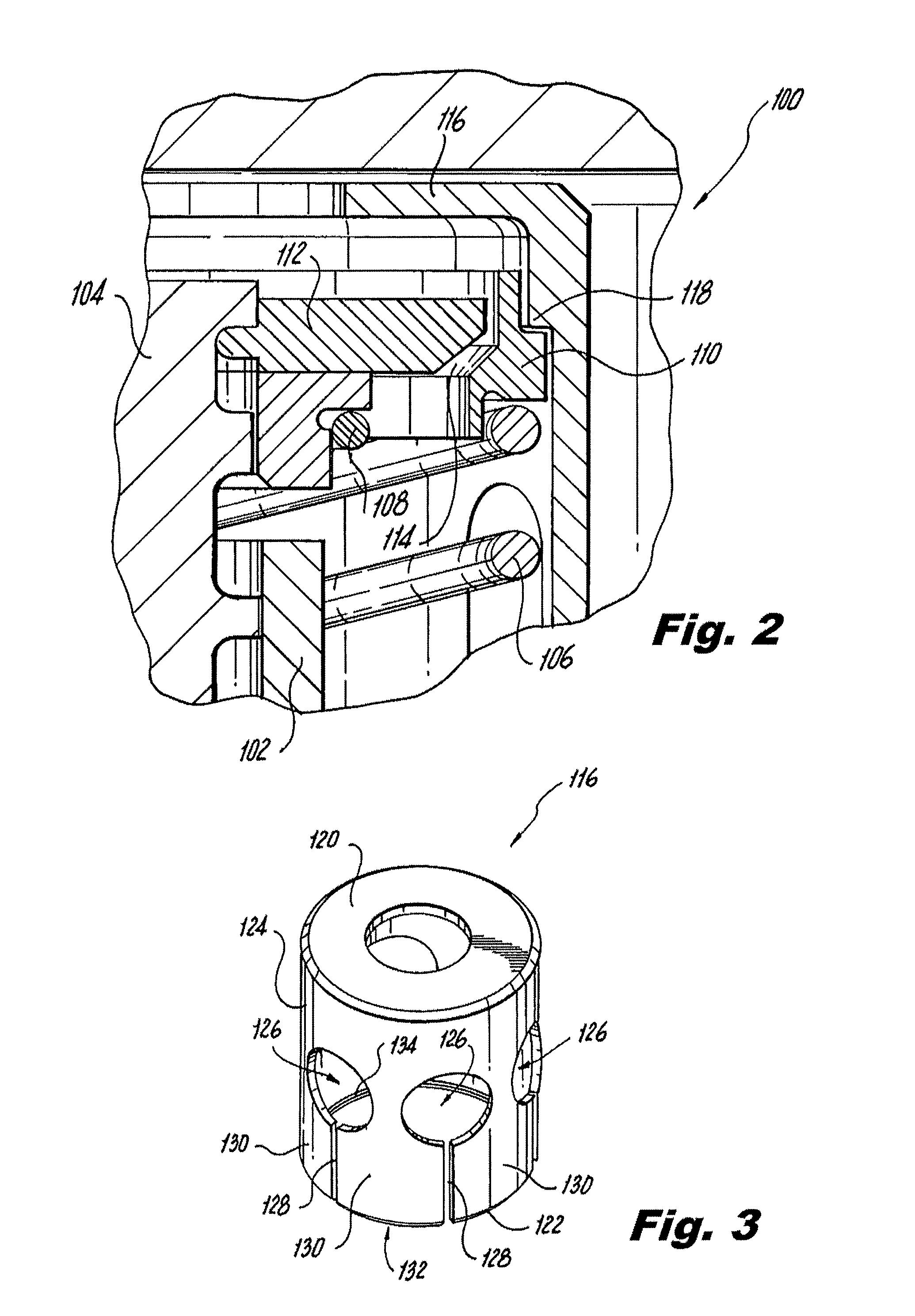
[0030]Reference will now be made to the drawings wherein like reference numerals identify similar structural features or aspects of the subject invention. For purposes of explanation and illustration, and not limitation, a partial view of an exemplary embodiment of a valve assembly constructed in accordance with the invention is shown in FIG. 1 and is designated generally by reference character 100. Other embodiments of valve assemblies in accordance with the invention, or aspects thereof, are provided in FIGS. 2-12, as will be described. The systems and methods of the invention can be used to improve precision and performance of valve assemblies, including for example, valve assemblies used in fuel injectors for gas turbine engines.

[0031]Referring now to FIG. 1, a fuel injector 10 constructed in accordance with the present invention is shown. Injector 10 includes an inlet section 12 that includes fuel inlet 14 and valve assembly 100. A mounting flange 16 is provided for attaching i...


PUM

PropertyMeasurementUnit
flexibleaaaaaaaaaa
specific flow ratesaaaaaaaaaa
pressureaaaaaaaaaa

Abstract

A pressure actuated valve assembly includes a valve body. The downstream end portion of a main spring is engaged with a downstream end portion of the valve body and the main spring is axially aligned with the valve body. A main spring guide is engaged with an upstream end portion of the main spring proximate an upstream end portion of the valve body. The main spring guide is mounted for movement toward the downstream end portion of the valve body by compression of the main spring. A hold-down sleeve is engaged with the downstream end portion of the valve body and includes a stop structure proximate the main spring guide. The stop structure is configured to engage the main spring guide to maintain a predetermined minimum clearance between the main spring guide and the upstream end portion of the valve body with the valve body in the closed condition.

Description

BACKGROUND OF THE INVENTION[0001]1. Field of the Invention[0002]The present invention relates to fluid control valves, and more particularly to pressure actuated valves for fuel injectors employed with gas turbine engines.[0003]2. Description of Related Art[0004]Pressure actuated valves are well known in the art, and one example is a valve assembly used in a fuel system to provide specific flow rates as a function of pressure. One particular application of such valves is in fuel injector systems of gas turbine engines.[0005]It is well known that in fuel supply systems of gas turbine engines, for example, it is desirable when the engine is shut down to preclude flow of even small amounts of fuel to the nozzles that deliver fuel to the combustion chamber. It is also desirable to open valves to provide an initial flow of fuel from the reservoir to the engine when a relatively low pressure differential exists between the reservoir and the engine, as during engine start up. In many appli...

Claims


Application Information

Patent Timeline
Patent Type & Authority Patents(United States)
IPC IPC(8): F02C1/00F01L3/10
CPCF02C9/263F16K17/06F02C7/232F16K17/044Y10T29/49826
Inventor DEATON, STEVEN SCOTTCANNY, JOHN DAVID
Owner COLLINS ENGINE NOZZLES INC
Why Eureka
Try Eureka