Light source unit and projector

a technology which is applied in the field of light source unit and projector, can solve the problems of insufficient red light, and achieve the effects of low luminous efficiency, good luminous efficiency, and increased screen luminan

Active Publication Date: 2013-10-15
CASIO COMPUTER CO LTD
View PDF42 Cites 10 Cited by
  • Summary
  • Abstract
  • Description
  • Claims
  • Application Information

AI Technical Summary

Benefits of technology

[0011]According to the invention, there can be provided the light source unit which can increase the luminance of the screen by comprising the light source which excites the luminescent material, the luminescent plate which has the luminescent material having the good luminous efficiency and the monochromatic light source which emits the light of wavelength band which corresponds to the luminescent material having the relatively low luminous efficiency, and the projector which comprises the light source unit.
[0012]In addition, the luminescent light emission portion and the diffuse transmission portion are formed on the luminescent plate of the light source unit, and the light of the plurality of wavelength bands in color can be emitted from the light source unit by causing the excitation light from the first light source unit and the monochromatic light from the second light source to be shone on to the luminescent plate. Thus, the light source unit with the simple configuration and the small projector which comprises the light source unit can be provided.

Problems solved by technology

However, the luminous efficiency of the red luminescent material is lower than those of the other luminescent materials, and therefore, in the event that the luminescent material layers are disposed substantially equally in area in the circumferential direction of the luminescent wheel, there is caused a problem that the luminance of red becomes insufficient.

Method used


Image

  • Light source unit and projector
  • Light source unit and projector
  • Light source unit and projector

Examples


Embodiment Construction

[0027]Hereinafter, a preferred mode for carrying out the invention will be described by use of the accompanying drawings. Although various limitations which are technically preferable in carrying out the invention are imposed on an embodiment which will be described below, the scope of the invention is not limited in any way by the following embodiment and illustrated examples.

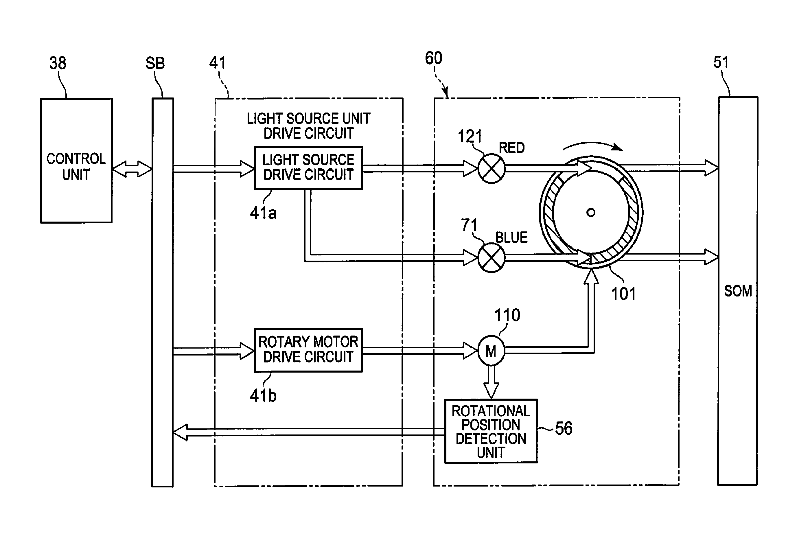
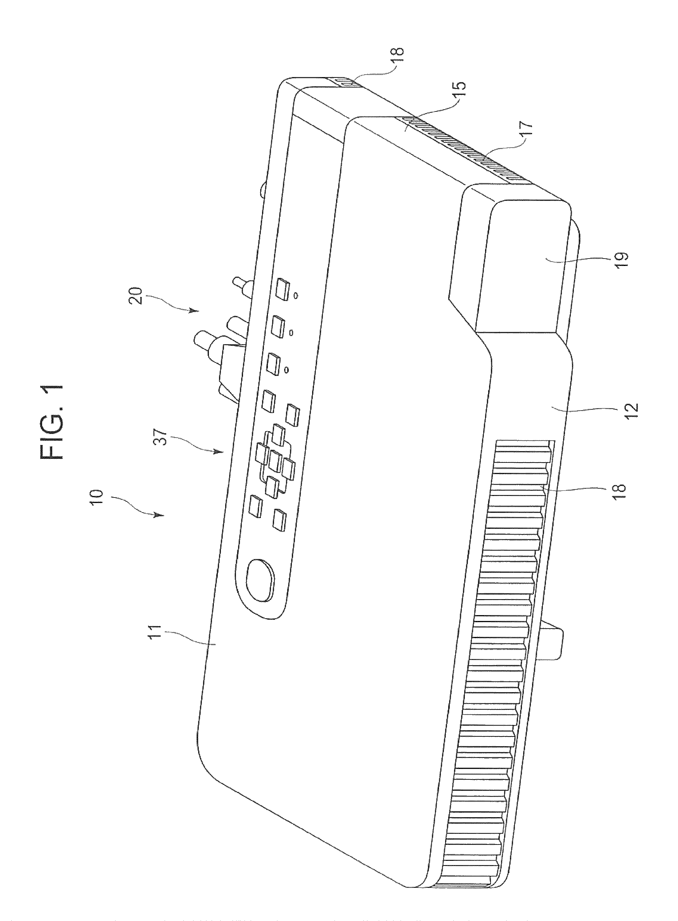
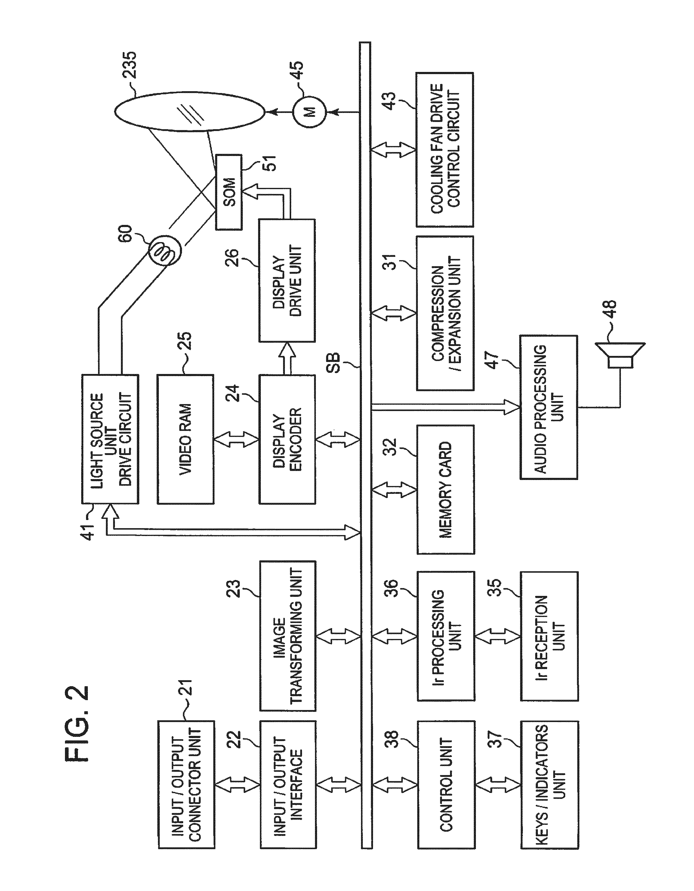
[0028]Hereinafter, a mode for carrying out the embodiment will be described. A projector 10 includes a light source unit 60, a display device 51, a light source side optical system 170 which collects light from the light source unit 60 to the display device 51, a projection side optical system 220 which projects an image emitted from the display device 51 on to a screen, and a projector control unit which controls the light source unit 60 and the display device 51. This projector control unit includes a light source control part which controls individually a first light source 71 and a second light source 121 ...


PUM


Abstract

There is provided a light source unit comprising a luminescent plate having a luminescent light emission portion and a diffuse transmission portion, a first light source which emits light of a wavelength band which can excite the luminescent material, a second light source which emits light of a wavelength band which differs from the luminous light and the light emitted from the first light source, a light guiding optical system which guides light of respective wavelength bands in color emitted from the luminescent plate to a predetermined plane, and a light source control part for controlling individually the emission of light from the first light source and the second light source, wherein the luminescent plate is disposed on optical paths of the first light source and the second light source, wherein a light shining position of light from the first light source and a light shining position of light from the second light source are made to differ from each other on the luminescent plate, and wherein the light source control part controls so that the first light source and the second light source emit light simultaneously or separately to thereby emit synthesized light or monochromatic light.

Description

CROSS-REFERENCE TO RELATED APPLICATIONS[0001]This application is based upon and claims the benefit of priority of Japanese Patent Application No. 2010-172644 filed on Jul. 30, 2010, the entire contents of which are to be incorporated herein by reference.BACKGROUND OF THE INVENTION[0002]1. Field of the Invention[0003]The present invention relates to a light source unit and a projector which includes the light source unit.[0004]2. Description of the Related Art[0005]In these days, data projectors are used on many occasions as image projection apparatuses which project images including images of screens and video images of personal computers, as well as images based on image data which is stored in memory cards on to a screen. These projectors are such that light emitted from a light source is collected to a display device such as a DMD (Digital Micromirror Device) and a liquid crystal plate for display of a color image onto the screen.[0006]Conventionally, in the mainstream of these p...

Claims


Application Information

Patent Timeline
Patent Type & Authority Patents(United States)
IPC IPC(8): G03B21/00G03B21/20G03B21/14G03B21/26
CPCG03B21/204G03B21/2013G03B21/208G03B21/145
Inventor MASUDA, HIROKI
Owner CASIO COMPUTER CO LTD
Why Eureka
Try Eureka