
Crank chamber communication structure of multi-cylinder internal combustion engine
a multi-cylinder internal combustion engine and communication structure technology, applied in the direction of machines/engines, cylinders, casings, etc., can solve the problems of difficult back-and-forth movement of air itself, inability to reduce pumping loss, and difficulty in adjusting the speed of the crank chamber communication structure, so as to reduce the pumping loss
- Summary
- Abstract
- Description
- Claims
- Application Information
AI Technical Summary
Benefits of technology
Problems solved by technology
Method used
Image

Examples
first embodiment
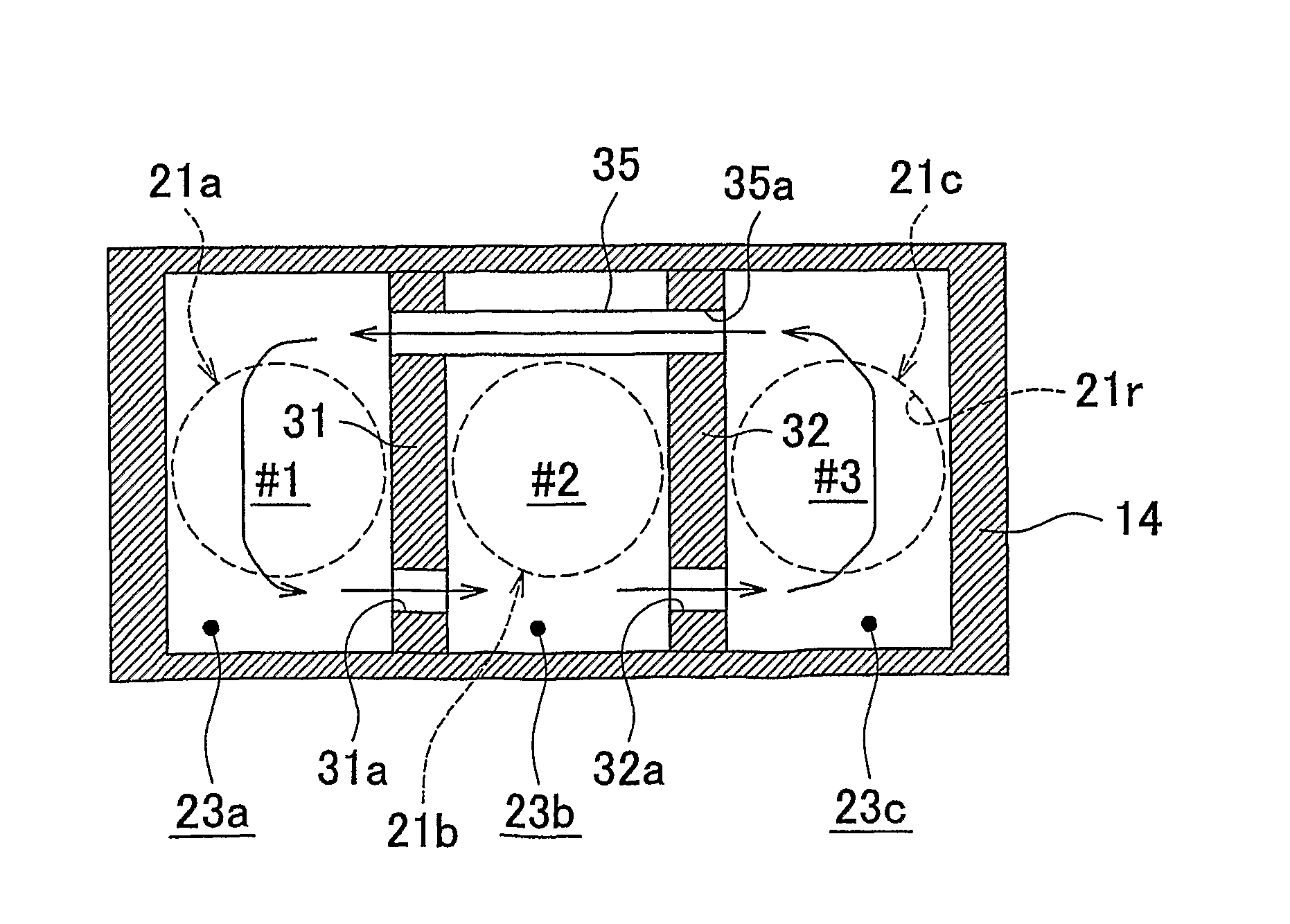
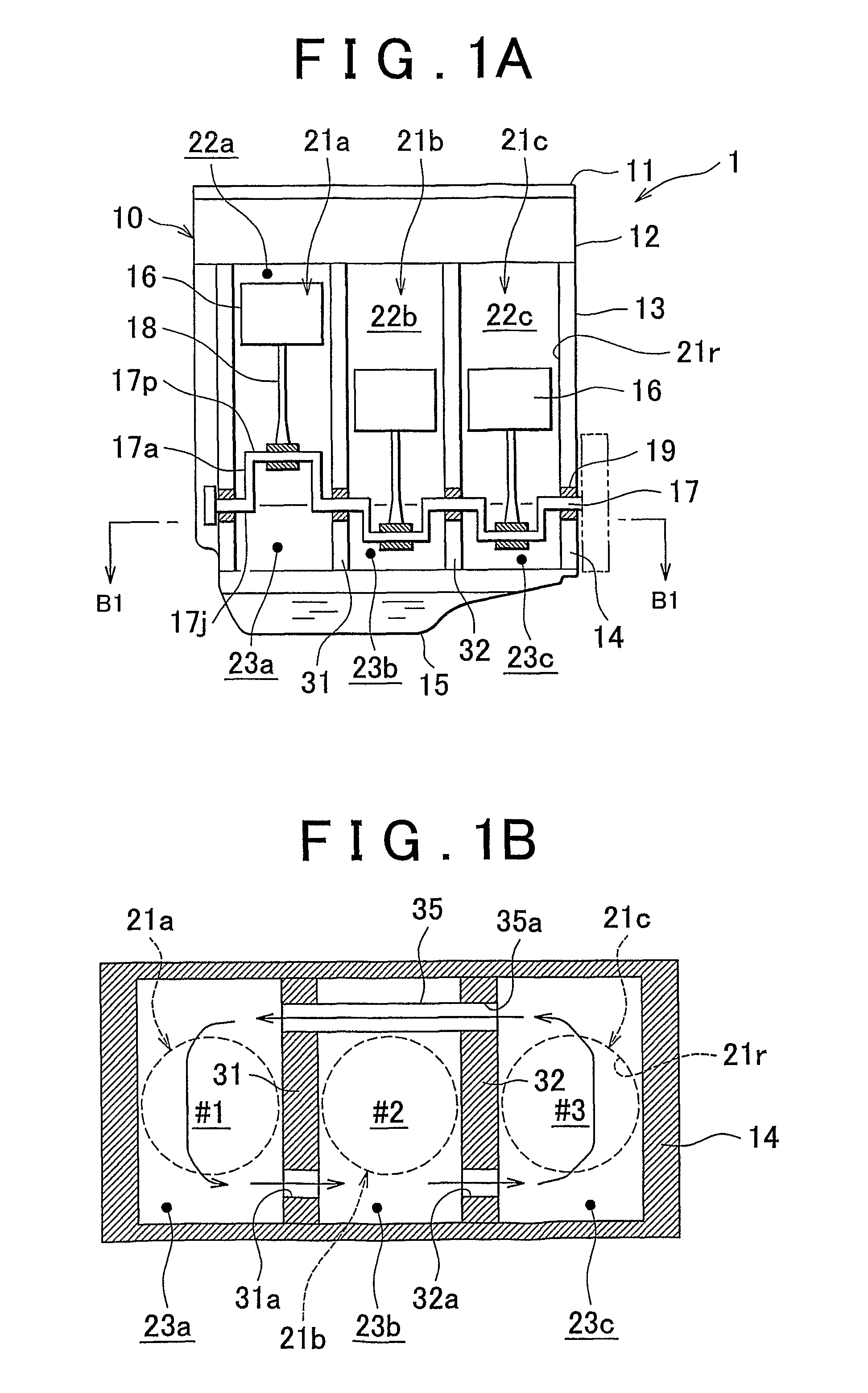
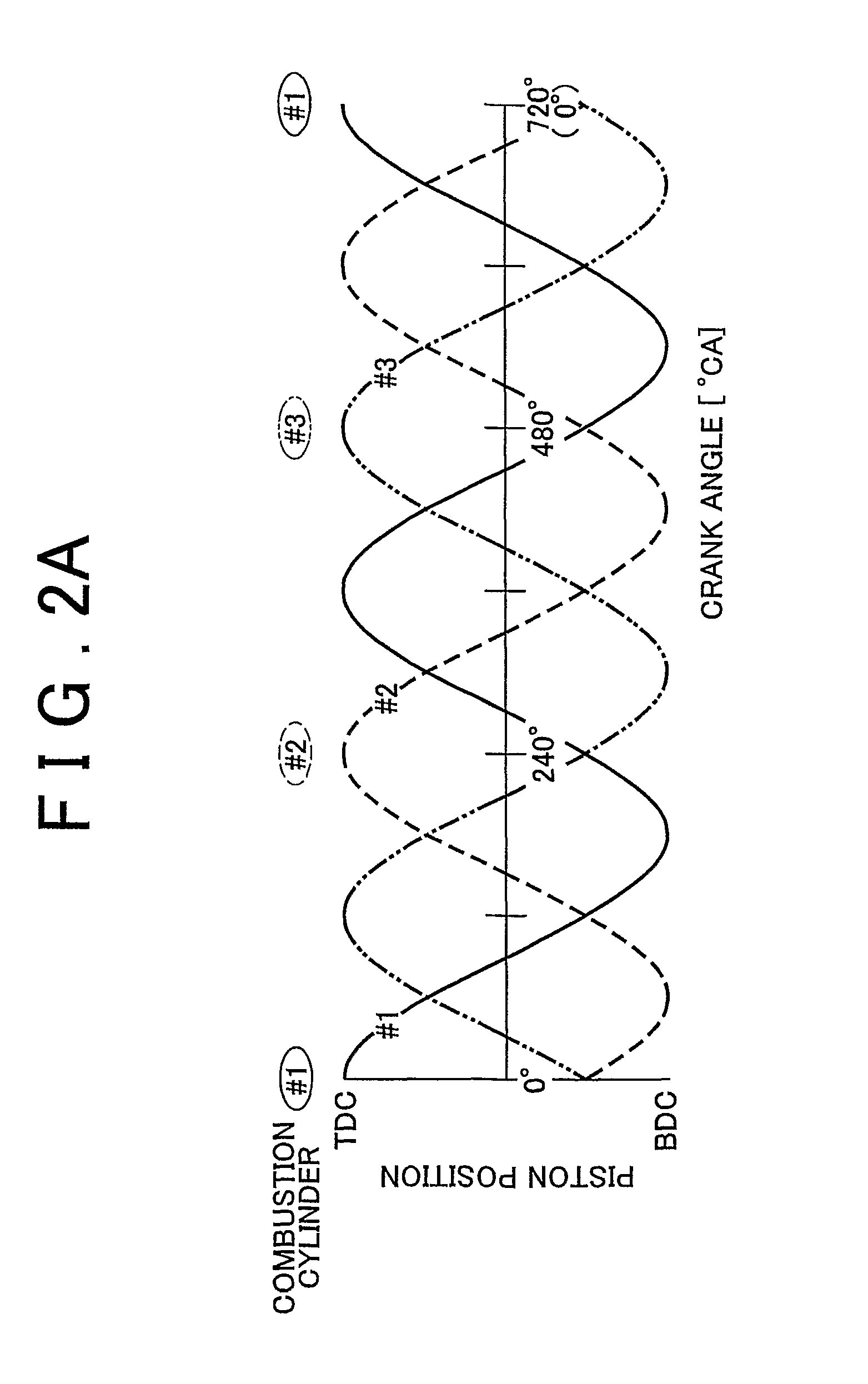
[0049]FIGS. 1 to 3 are diagrams that show a crank chamber communication structure of a multi-cylinder internal combustion engine in accordance with the present invention, and show an engine that is installed as a multi-cylinder internal combustion engine in an automobile.
[0050]First, a configuration of the multi-cylinder internal combustion engine in accordance with the first embodiment of the present invention will be described.
[0051]The engine 1 shown in FIG. 1A in a cross section includes an engine main body 10 that has, in the order from the top, a head cover 11, a cylinder head 12, a cylinder block 13, a crank case 14, and an oil pan 15. The engine main body 10 has three cylinders 21a, 21b, and 21c. Each of the cylinders 21a to 21c houses a piston 16. A crankshaft 17 is connected to the piston 16 via the connecting rod 18. Further, conventional valve mechanisms and ignition devices of a spark ignition type (all not shown) are housed inside an upper section of the engine main bo...
third embodiment
[0087]FIGS. 6 and 7 show a crank chamber communication structure of a multi-cylinder internal combustion engine in accordance with the present invention. In FIG. 6, both lateral side walls of the crankcase and the crankshaft are not shown.
[0088]As shown in FIG. 6, an engine 6 of this embodiment is an in-line six-cylinder internal combustion engine type. The engine main body 60 has six cylinders 61a, 61b, 61c, 61d, 61e, and 61f. In the engine main body 60, a cylinder block (not shown) that has cylinder bores 61r which correspond to the six cylinders and a crankcase 64 that is fastened and fixed to the cylinder block by a plurality of bolts (not shown) form a plurality of partition walls 71, 72, 73, 74, and 75 that support a crankshaft (not shown). The plurality of partition walls 71 to 75 define and form a plurality of crank chambers 63a, 63b, 63c, 63d, 63e, and 63f that correspond to the plurality of cylinders 61a to 61f.
[0089]The four partition walls 71, 72, 74, and 75 among the p...
PUM
 Abstract
Description
Claims
Application Information