Split Stirling Expansion Machine

An expander, separate technology, used in refrigerators, compressors, mechanical equipment, etc., can solve the problem of cooling efficiency decline, and achieve the effect of reducing dead volume, convenient processing and manufacturing, and reducing weight and volume.

Pending Publication Date: 2020-01-31
UNIV OF SHANGHAI FOR SCI & TECH
View PDF0 Cites 2 Cited by
  • Summary
  • Abstract
  • Description
  • Claims
  • Application Information

AI Technical Summary

Problems solved by technology

For occasions with small cooling capacity requirements, in order to simplify the structure and optimize the volume, the expander often does not install a heat sink at the hot end, resulting in a decrease in cooling efficiency

Method used


Image

  • Split Stirling Expansion Machine
  • Split Stirling Expansion Machine
  • Split Stirling Expansion Machine

Examples


Embodiment 1

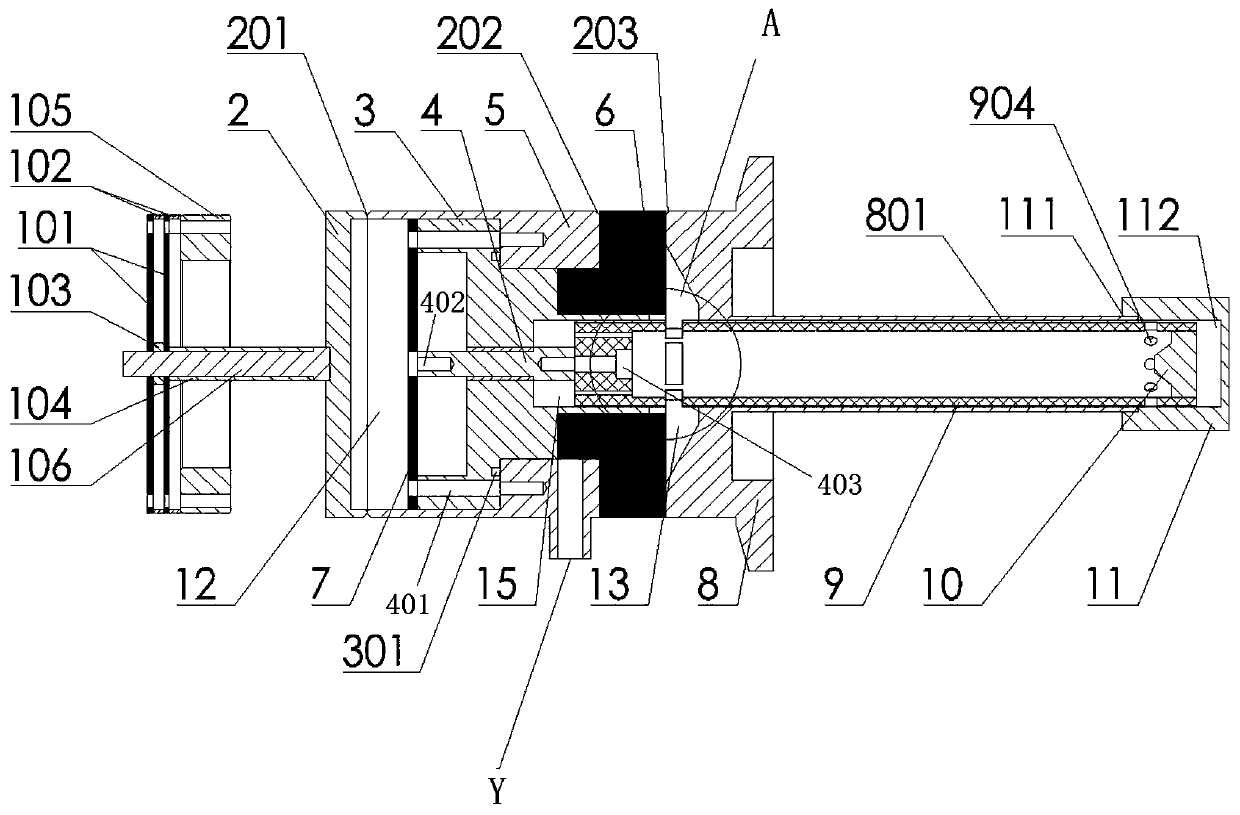
[0034] The split Stirling expander includes a shell unit, a motion unit and a shock absorber unit.

[0035] Such as figure 1 and figure 2 as shown,

[0036] The shell unit includes a bottom shell 2 , a middle shell 5 , a slit heat exchanger 6 , an expansion cylinder 8 , an inner liner 3 and a cold head 11 which are connected in sequence.

[0037] In the embodiment, the bottom shell 2 is disc-shaped.

[0038] The middle shell 5 is cylindrical, with openings at both ends, and has two connected coaxial cylindrical cavities inside, and the two cavities have different diameters. The end with a larger diameter of the cavity is connected to the bottom shell 2 , and the bottom shell 2 and the middle shell 5 are welded at the welding port 201 .

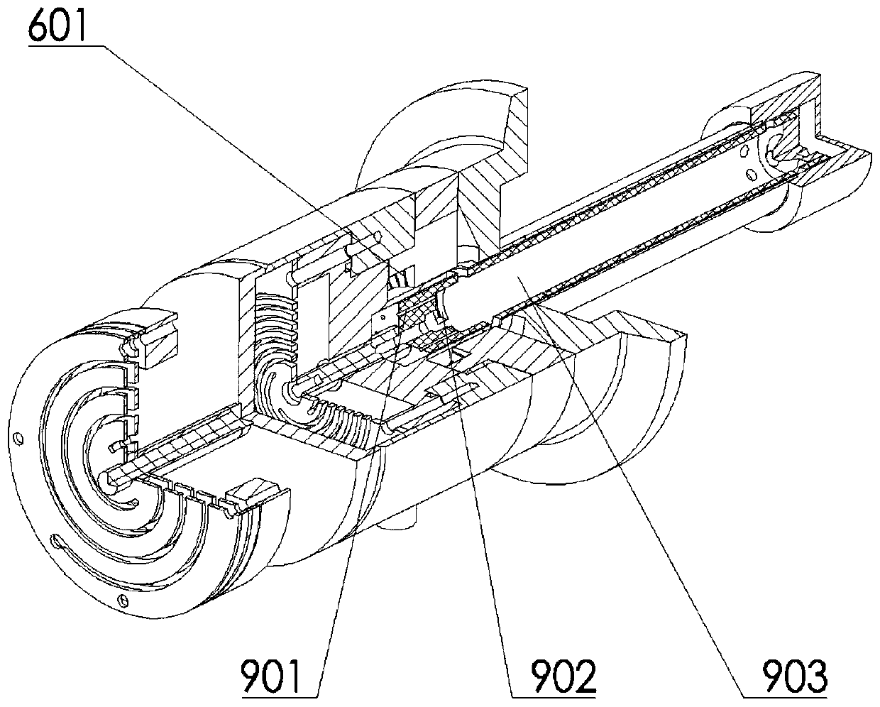
[0039] Such as Figure 5 , 6 As shown, the slit heat exchanger 6 is a hot-end heat exchanger, which is sandwiched between the middle shell 5 and the expansion cylinder 8. The slit heat exchanger 6 is in the shape of a flange and has a c...

Embodiment 2

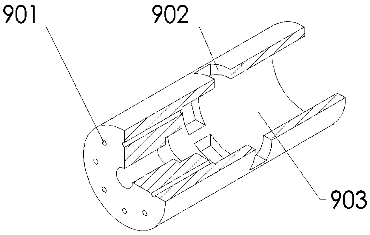
[0065] The structure of this embodiment is the same as that of the first embodiment, except that the structure of the regenerator shell 14 in this embodiment is different from that of the regenerator shell 9 in the first embodiment.

[0066] Such as Figure 10 As shown, in this embodiment, there is no vent hole on the bottom end surface of the regenerator shell 14, and there is a gap between the cylindrical surface of the regenerator shell 14 and the inner wall surface of the inner bushing 3, and the unilateral gap is 0.3-0.5 mm. The shell main chamber 13 and the shell sub-chamber 15 are connected through a gap. During the operation of the expander, the pressures in the shell main chamber 13 and the shell sub-chamber 15 always maintain a dynamic balance, which is beneficial to reduce the pressure on the regenerator shell 9. Radial vibration ensures the stability of the operating conditions of the expander.

[0067] Function and effect of embodiment

[0068] According to the ...


PUM


Abstract

The invention discloses a split Stirling expansion machine. The split Stirling expansion machine comprises a shell unit and a motion unit, the shell unit comprises a bottom shell, a middle shell, a slit heat exchanger, an expansion cylinder, an inner liner and a cold head which are connected in sequence, one end of the slit heat exchanger is connected with one end of the expansion cylinder, the inner liner is arranged in the middle shell, the side surface and the end surface of the inner liner are connected with the middle shell and a small disc respectively, the motion unit comprises an expansion machine plate spring, an evacuator rod and a regenerator shell, the expansion machine plate spring is fixedly connected with the inner liner, one end of the regenerator shell is arranged in the inner liner, the other end of the regenerator shell is arranged in the cylindrical air cylinder, and the evacuator rod is arranged in the inner liner. According to the expansion machine, a traditionalwater cooling sleeve structure is eliminated, a hot end slit type heat exchanger is adopted for replacing, gas working medium releases enough heat to the environment through the hot end heat exchanger, and the requirements of the expansion machine on the gas working medium heat dissipation amount under different working conditions can be correspondingly met by changing the number, the width and the like of the slits of the hot end heat exchanger.

Description

technical field [0001] The invention belongs to the refrigeration field, and in particular relates to a split Stirling expander. Background technique [0002] Since the development of cryogenic refrigerators, they have been widely used in commercial, military and space refrigeration fields. As a typical type of regenerative cryogenic refrigerators, Stirling refrigerators should initially be used in aerospace, superconducting filtering, infrared detection and other fields. Compared with the traditional vapor compression refrigeration, the Stirling refrigerator has many advantages such as environmental protection of refrigerant, no limitation of working direction, compact structure, high efficiency and reliability. [0003] According to the connection mode of the expansion chamber and the compression chamber, the Stirling refrigerator can be divided into separate type and integral type. The split Stirling refrigerator is developed on the basis of the research on the integral...

Claims


Application Information

Patent Timeline
Patent Type & Authority Applications(China)
IPC IPC(8): F25B9/14F25B41/06F25B39/00F25B41/30
CPCF25B9/14F25B39/00F25B41/31
Inventor 陈曦洪昊倪贤灿梁天晓
Owner UNIV OF SHANGHAI FOR SCI & TECH
Why Eureka
Try Eureka