Air valve lifting device for engine, engine comprising same, and automobile comprising same

A valve lift and engine technology, which is applied in the fields of vehicles, valve lift devices and engines, can solve the problems of reducing the working efficiency of the engine and increasing the mechanical loss and power, and achieves the goal of reducing the pumping loss and mechanical loss and improving the working efficiency. Effect

Active Publication Date: 2013-07-24
GREAT WALL MOTOR CO LTD
View PDF5 Cites 1 Cited by
  • Summary
  • Abstract
  • Description
  • Claims
  • Application Information

AI Technical Summary

Problems solved by technology

Generally, the size of the engine valve lift is designed according to the requirements of high speed and heavy load conditions, mainly to ensure the power output under high speed and heavy loads, so there is an excessive opening phenomenon of the valve under low speed and small load conditions; Under the condition of low speed and small load, on the one hand, the intake air volume is adjusted by reducing the opening of the throttle valve; reduced engine efficiency

Method used


Image

  • Air valve lifting device for engine, engine comprising same, and automobile comprising same
  • Air valve lifting device for engine, engine comprising same, and automobile comprising same
  • Air valve lifting device for engine, engine comprising same, and automobile comprising same

Examples


Embodiment Construction

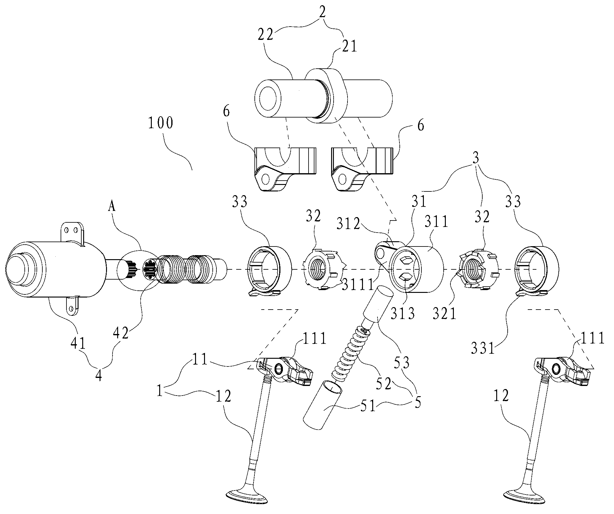
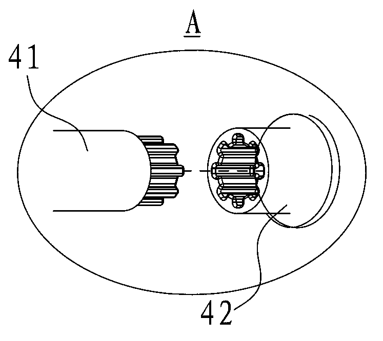
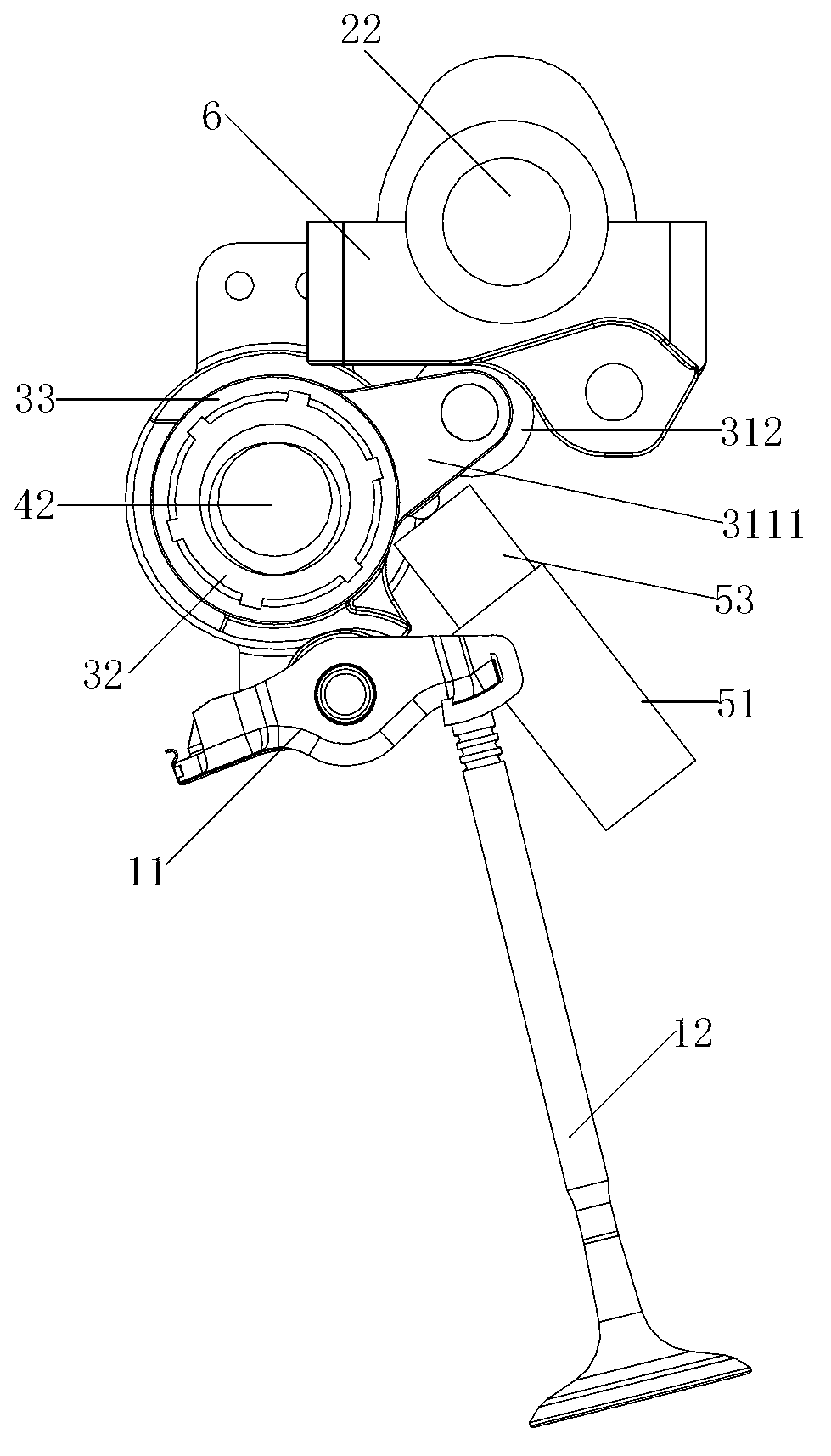
[0023] Embodiments of the present invention are described in detail below, examples of which are shown in the drawings, wherein the same or similar reference numerals designate the same or similar elements or elements having the same or similar functions throughout. The embodiments described below by referring to the figures are exemplary only for explaining the present invention and should not be construed as limiting the present invention.

[0024] In describing the present invention, it should be understood that the terms "central", "lateral", "upper", "lower", "front", "rear", "left", "right", "vertical", The orientations or positional relationships indicated by "horizontal", "top", "bottom", "inner", "outer", etc. are based on the orientation or positional relationships shown in the drawings, and are only for the convenience of describing the present invention and simplifying the description, and It is not to indicate or imply that the device or element referred to must h...


PUM


Abstract

The invention discloses an air valve lifting device for an engine, the engine comprising the same, and an automobile comprising the same. The air valve lifting device comprises an air valve mechanism, a cam shaft mechanism, a swing arm mechanism and an actuating mechanism, wherein the top of the air valve mechanism is provided with a roller arm, the cam shaft mechanism is arranged above the air valve mechanism, the cam shaft mechanism comprises a cam, the swing arm mechanism is arranged between the roller arm and the cam shaft mechanism and is driven by the cam to swing around the swing arm rotary axis of the swing arm mechanism, the actuating mechanism is used for driving the swing arm mechanism to rotate around the regulating rotary axis of the actuating mechanism to continuously and changeably regulate the lift of the air valve mechanism, and the swing arm rotary axis is coincident with the regulating rotary axis. According to the air valve lifting device, different air valve lifts can be achieved according to requirements of different working conditions of the engine, and pump gas loss and mechanical loss in the low-speed load working condition are reduced. Meanwhile, continuation and changeability of the air valve lifts are achieved, and work efficiency of the engine is improved.

Description

technical field [0001] The invention relates to the field of automobiles, in particular to a valve lift device for an engine, an engine and a vehicle with the same. Background technique [0002] The valve lift and valve wrap angle of the traditional engine valve train are fixed, and the lift depends on the designed working point, which is determined by the shape of the cam and the structure of the roller rocker arm. The operating conditions of the engine have different requirements for valve lift and wrap angle. High-speed and heavy-load conditions require large valve lift and large valve wrap angle, while low-speed and light-load conditions require small valve lift and small wrap angle. Generally, the size of the engine valve lift is designed according to the requirements of high speed and heavy load conditions, mainly to ensure the power output under high speed and heavy loads, so there is an excessive opening phenomenon of the valve under low speed and small load conditio...

Claims


Application Information

Patent Timeline
Patent Type & Authority Applications(China)
IPC IPC(8): F01L13/00
Inventor 刘涛刘胜强王龙尹吉
Owner GREAT WALL MOTOR CO LTD
Why Eureka
Try Eureka