Crank chamber communication structure of multi-cylinder internal combustion engine

a multi-cylinder internal combustion engine and communication structure technology, applied in the direction of machines/engines, cylinders, casings, etc., can solve the problems of difficult back-and-forth movement of air itself, inability to reduce pumping loss, and difficulty in adjusting the speed of the crank chamber communication structure, so as to reduce the pumping loss

Inactive Publication Date: 2011-11-24
TOYOTA JIDOSHA KK
View PDF0 Cites 2 Cited by
  • Summary
  • Abstract
  • Description
  • Claims
  • Application Information

AI Technical Summary

Benefits of technology

[0011]The present invention provides a crank chamber communication structure of a multi-cylinder internal combustion engine that can more certainly reduce pumping loss.

Problems solved by technology

However, in multi-cylinder engines in which the relationship cannot be achieved such that the phases of the pistons are opposite between the adjoining cylinders, such as in-line multi-cylinder engines that have three cylinders, five cylinders, six or more cylinders and V-type engines, pumping loss cannot be certainly reduced.
This results in pumping loss.
Further, in the multi-cylinder engines in which the relationship cannot be achieved such that the phases of the pistons are opposite between the adjoining cylinders, because there is no point that speeds of the pistons of the adjoining cylinders simultaneously becomes zero, the back-and-forth movement of the air itself becomes very complicated.
Therefore, pumping loss is apt to occur not only at the cylinder that is positioned at the end but also at the other cylinders.

Method used


Image

  • Crank chamber communication structure of multi-cylinder internal combustion engine
  • Crank chamber communication structure of multi-cylinder internal combustion engine
  • Crank chamber communication structure of multi-cylinder internal combustion engine

Examples


first embodiment

[0049]FIGS. 1 to 3 are diagrams that show a crank chamber communication structure of a multi-cylinder internal combustion engine in accordance with the present invention, and show an engine that is installed as a multi-cylinder internal combustion engine in an automobile.

[0050]First, a configuration of the multi-cylinder internal combustion engine in accordance with the first embodiment of the present invention will be described.

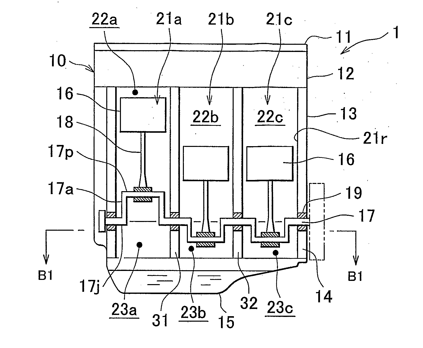
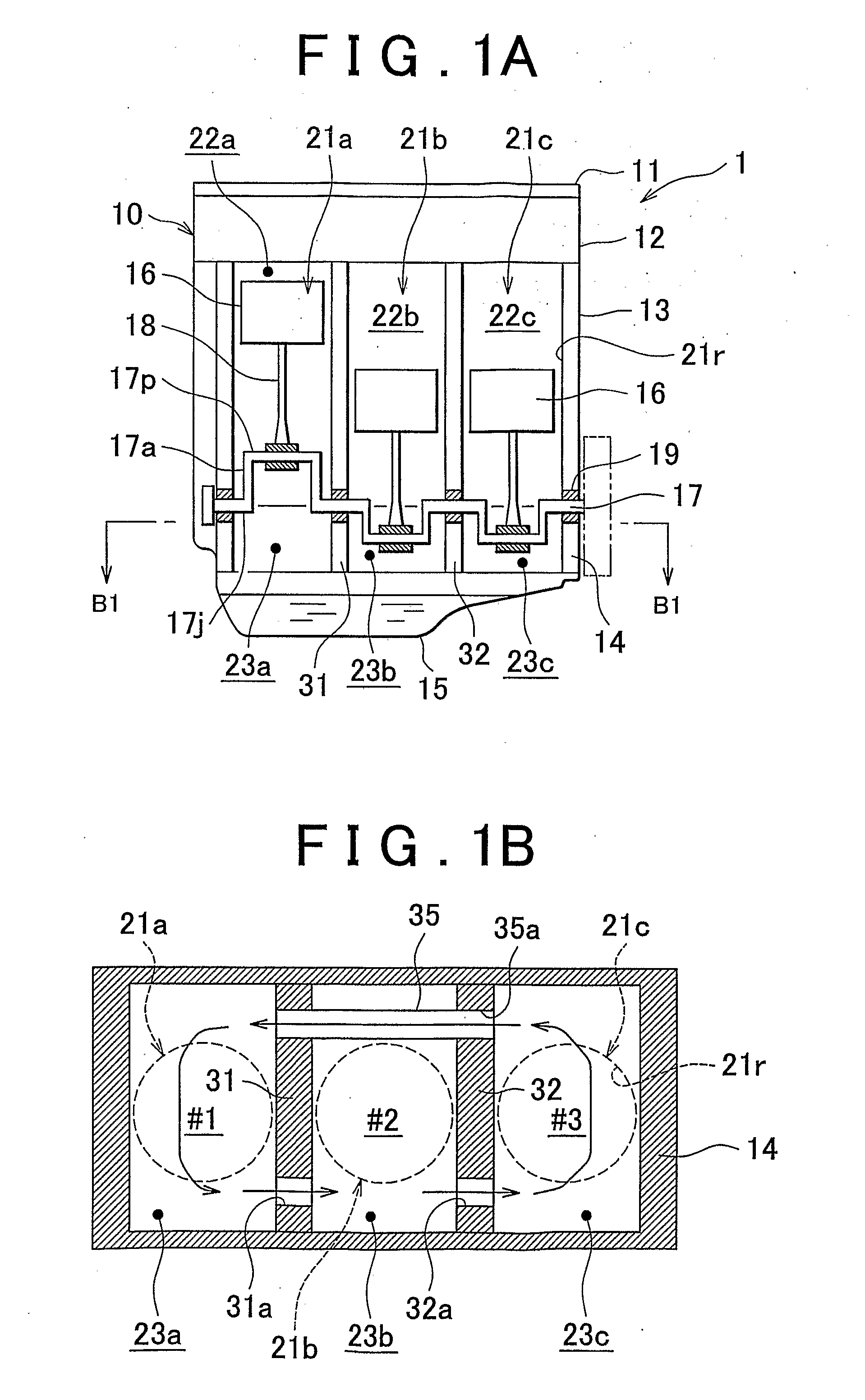
[0051]The engine 1 shown in FIG. 1A in a cross section includes an engine main body 10 that has, in the order from the top, a head cover 11, a cylinder head 12, a cylinder block 13, a crank case 14, and an oil pan 15. The engine main body 10 has three cylinders 21a, 21b, and 21c. Each of the cylinders 21a to 21c houses a piston 16. A crankshaft 17 is connected to the piston 16 via the connecting rod 18. Further, conventional valve mechanisms and ignition devices of a spark ignition type (all not shown) are housed inside an upper section of the engine main bo...

third embodiment

[0087]FIGS. 6 and 7 show a crank chamber communication structure of a multi-cylinder internal combustion engine in accordance with the present invention. In FIG. 6, both lateral side walls of the crankcase and the crankshaft are not shown.

[0088]As shown in FIG. 6, an engine 6 of this embodiment is an in-line six-cylinder internal combustion engine type. The engine main body 60 has six cylinders 61a, 61b, 61c, 61d, 61e, and 61f. In the engine main body 60, a cylinder block (not shown) that has cylinder bores 61r which correspond to the six cylinders and a crankcase 64 that is fastened and fixed to the cylinder block by a plurality of bolts (not shown) form a plurality of partition walls 71, 72, 73, 74, and 75 that support a crankshaft (not shown). The plurality of partition walls 71 to 75 define and form a plurality of crank chambers 63a, 63b, 63c, 63d, 63e, and 63f that correspond to the plurality of cylinders 61a to 61f.

[0089]The four partition walls 71, 72, 74, and 75 among the p...


PUM


Abstract

A crank chamber communication structure for a multi-cylinder internal combustion engine having a plurality of partition walls that are formed by a cylinder block and a crankcase, that are formed to support a crankshaft and to define a plurality of crank chambers that correspond to the plurality of cylinders, the structure including: a plurality of respective first communicating holes formed in the plurality of partition walls for communication between respective pairs of adjoining crank chambers separated by an interposed partition wall; and a second communicating hole that is formed at least either of the cylinder block or the crankcase, and that is interposed between a pair of non-adjoining crank chambers between which at least two partition walls among the plurality of partition walls are interposed for direct communication between the pair of non-adjoining crank chambers.

Description

BACKGROUND OF THE INVENTION[0001]1. Field of the Invention[0002]The present invention relates to a crank chamber communication structure of a multi-cylinder internal combustion engine, and particularly relates to a crank chamber communication structure of a multi-cylinder internal combustion engine in which a breather is formed between adjoining crank chambers in a crankcase.[0003]2. Description of the Related Art[0004]In a multi-cylinder internal combustion engine, the propulsive force of pistons that receive combustion pressure in cylinders is transmitted to the crankpins of a crankshaft corresponding to the respective cylinders, and the propulsive force is converted into rotation of the crankshaft. Therefore, the crankshaft is often supported by partition walls that are disposed between spaces in the crankcase that correspond to an adjoining cylinder, in other words, a crank chamber via bearings. Further, because pumping loss may be reduced when air (including air, blow-by gas, a...

Claims


Application Information

Patent Timeline
Patent Type & Authority Applications(United States)
IPC IPC(8): F02F7/00
CPCF02B2075/1812F02B2075/182F02F7/0068F02F7/00F02B2075/1824
Inventor FUJII, MANABU
Owner TOYOTA JIDOSHA KK
Why Eureka
Try Eureka