Horizontal moving mechanical regulation system

A technology of mechanical adjustment and left and right movement, applied to mechanical equipment, combustion engines, machines/engines, etc., can solve problems such as the complex structure of the booster system, and achieve the effect of simple structure and reasonable design

Inactive Publication Date: 2013-02-06
SHANGHAI JIAO TONG UNIV
View PDF6 Cites 1 Cited by
  • Summary
  • Abstract
  • Description
  • Claims
  • Application Information

AI Technical Summary

Problems solved by technology

[0003] After searching the existing technical literature, it is found that Chinese patent number ZL200820226936.6, patent name: a compressor parallel supercharging device for a turbocharger, this patent technology provides a device with a variable compressor shell, It can better take into account the high and low speed conditions of the engine; but the change of its housing requires a special control mechanism, which makes the structure of the booster system more complicated

Method used


Image

  • Horizontal moving mechanical regulation system
  • Horizontal moving mechanical regulation system

Examples


Embodiment

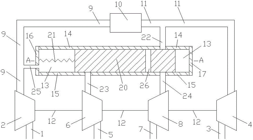
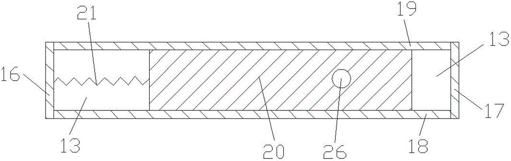
[0014] Such as figure 1 and figure 2 As shown, the present invention includes: a first air suction pipe 1, a first air compressor 2, a first air outlet pipe 3, a first turbine 4, a second air suction pipe 5, a second air compressor 6, a second air outlet pipe 7, Second turbine 8, engine intake pipe 9, engine 10, engine exhaust pipe 11, connecting shaft 12, volume cavity 13, volume cavity upper wall 14, volume cavity lower wall 15, volume cavity left wall 16, volume cavity right wall 17 , volume chamber front wall 18, volume chamber rear wall 19, moving body 20, spring 21, first connecting pipe 22, second connecting pipe 23, third connecting pipe 24, fourth connecting pipe 25 and through pipe 26, the first The air inlet and outlet of the compressor 2 are connected with the air outlet of the first air intake pipe 1 and the air inlet of the engine intake pipe 9 respectively, and the air inlet of the second air compressor 6 is connected with the air outlet of the second air inta...


PUM


Abstract

A horizontal moving mechanical regulation system in the technical field of combustion engines comprises compressors, a gas inlet pipe, an engine, an exhaust pipe, turbines, a volume cavity, a connection pipe, a moving body, a spring and a through pipe; the moving body is mounted in the volume cavity and is in sealed contact with the inner wall surface of the volume cavity, the through pipe penetrates through the upper and lower wall surfaces of the moving body, and the left wall surface of the moving body is connected with the left wall surface of the volume cavity through the spring. When the engine in a high speed work condition, the moving body moves towards the right, the first compressor, the second compressor, the first turbine and the second turbine works at the same time, so that the pumping loss of the engine is less and the performance of the whole engine is better; when the engine is in a low speed work condition, the moving body moves towards the left, only the first compressor and the first turbine work, so that the pulse energy is fully used, the gas inlet pressure of the engine is higher, and the performance of the whole engine is better. The horizontal moving mechanical regulation system is reasonable in design and simple in structure, and is applicable to a turbine pressurization system with dual turbines and double compressors.

Description

technical field [0001] The invention relates to a turbocharging system in the field of internal combustion engines, in particular to a left and right moving mechanical adjustment system. Background technique [0002] With the development of society and the improvement of environmental protection requirements, the application of engine supercharging technology is becoming more and more extensive. Most of the engines with medium and high power adopt turbocharging technology to improve power and reduce fuel consumption. The two basic types of turbocharging systems are constant pressure supercharging system and pulse supercharging system. Constant-pressure supercharging system, each cylinder shares a large-volume exhaust pipe, the structure of the exhaust pipe system is relatively simple, the equivalent flow area of ​​the turbine is relatively large, the pressure in the exhaust pipe is basically kept constant, and the pressure is only related to the load of the engine It is rel...

Claims


Application Information

Patent Timeline
Patent Type & Authority Applications(China)
IPC IPC(8): F02B37/12F02B37/007
CPCY02T10/144Y02T10/12
Inventor 张保华宋佳昊雷威莫迪杨海燕刘佳昱凌晓贡亮
Owner SHANGHAI JIAO TONG UNIV
Why Eureka
Try Eureka