Hip implant with porous body

a technology of implanted body and body, which is applied in the field of implanted body with porous body, can solve the problems of limited bone growth depth into the implant, bone simply cannot grow fully through the implant or deeply into the implant body,

Inactive Publication Date: 2014-09-02
FOUR MILE BAY
View PDF10 Cites 12 Cited by
  • Summary
  • Abstract
  • Description
  • Claims
  • Application Information

AI Technical Summary

Problems solved by technology

The depth of bone growth into the implant is limited to the depth of the porous coating.
Bon

Method used


Image

  • Hip implant with porous body
  • Hip implant with porous body
  • Hip implant with porous body

Examples


Embodiment Construction

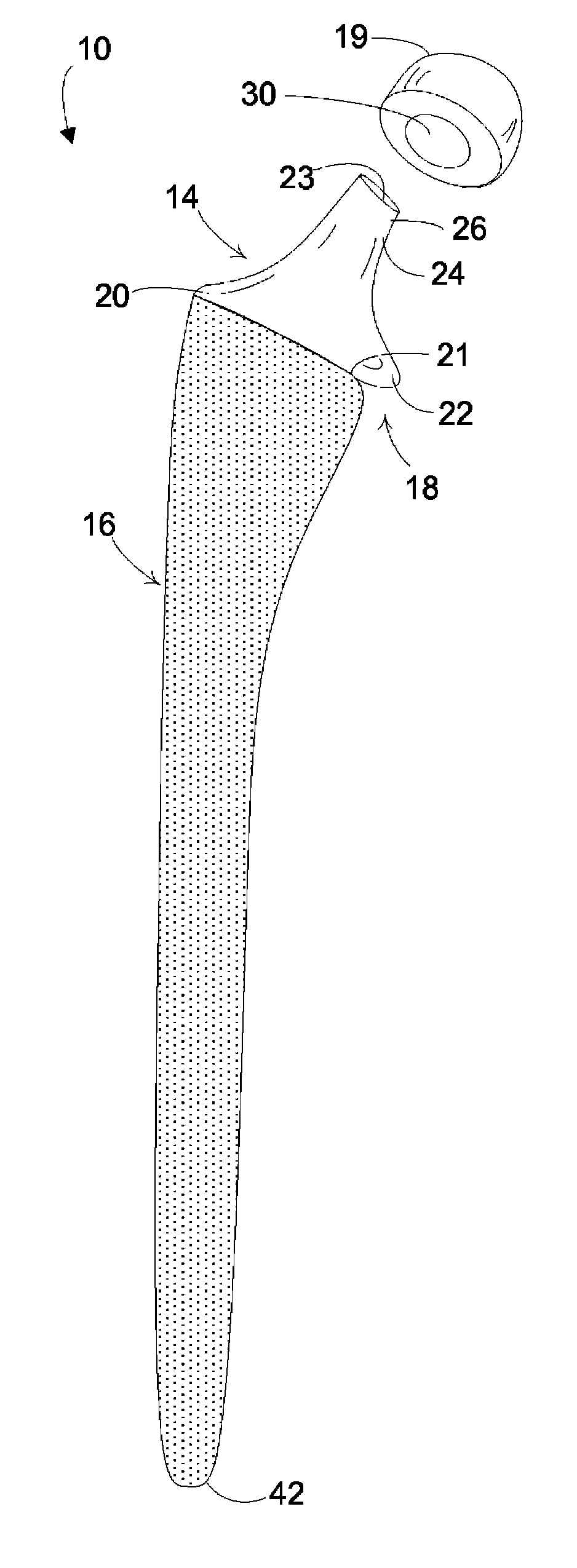
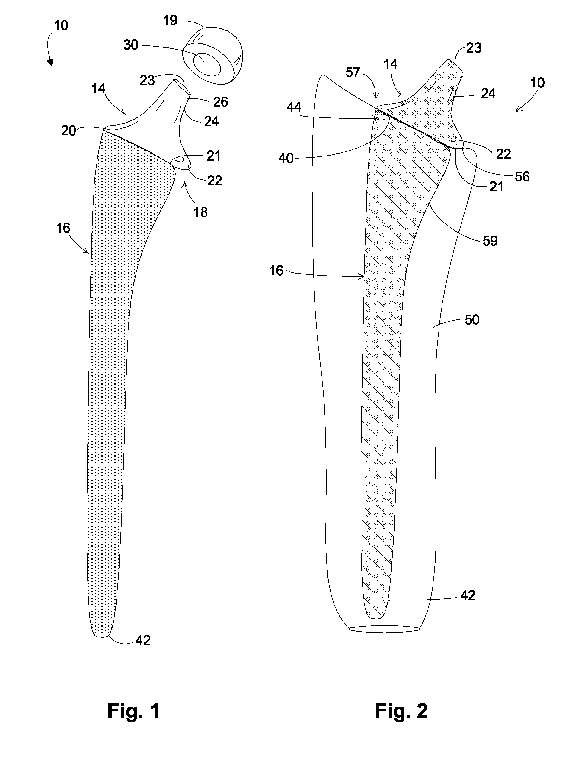
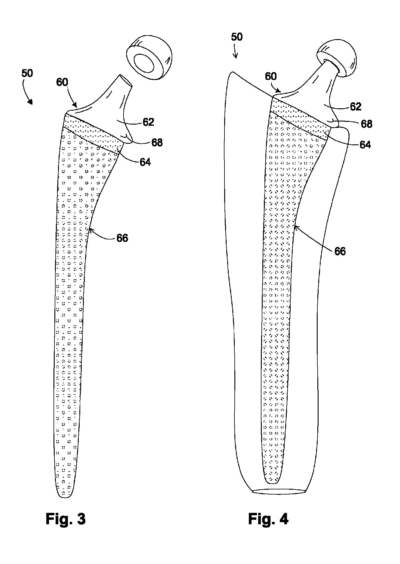
[0028]In one example embodiment, a hip implant includes two separate and distinct bodies, a neck body and a bone fixation body. Together, these bodies connect together to form a femoral hip implant.

[0029]The bone fixation body is formed of a porous structure, such as titanium, tantalum, or other metals, polymers, or alloys suitable for a hip prosthesis. The bone fixation body has at least one cross-section in which the porous structure is completely porous. This completely porous structure can extend through a portion of the bone fixation body (e.g., throughout a cross-section) or through the entire body of the bone fixation body. For example in one embodiment, the bone fixation body is completely porous from its proximal to distal ends and does not include a metal substrate. In another example embodiment, a portion of the bone fixation body is completely porous and does not include a metal substrate. In at least one cross-sectional view then, the bone fixation body has a porous str...


PUM

PropertyMeasurementUnit
Structureaaaaaaaaaa
Shapeaaaaaaaaaa
Areaaaaaaaaaaa

Abstract

A hip implant has a neck body that connects to a bone fixation body. The bone fixation body has a porous structure with an elongated shape. An internal cavity is formed in the bone fixation body and includes a substance to stimulate bone growth.

Description

CROSS-REFERENCE TO RELATED APPLICATIONS[0001]This application is a continuation-in-part of Ser. No. 11 / 409,611 filed on 24 Apr. 2006 now U.S. Pat. No. 8,506,642, which is a continuing application of Ser. No. 10 / 446,069 filed on May 27, 2003 now abandoned, both entitled “Hip Implant with Porous Body” and both being incorporated herein by reference.BACKGROUND OF THE INVENTION[0002]Much effort has been directed to integrating hip implants into surrounding bone. Ideally, a hip implant would be placed into the femur, and thereafter bone would readily grow into the surface of the implant. To achieve this objective, many different surface technologies have been applied to hip implants. In some instances, the surface of the implant is roughened, grit-blasted, plasma-sprayed, or microtextured. In other instances, the surface is coated with a biological agent, such as hydroxylapatite (known as HA). In all of these instances, the goal is the same: Produce a surface on the hip implant into whic...

Claims


Application Information

Patent Timeline
IPC IPC(8): A61F2/32
CPCA61F2002/3092A61F2002/30403A61F2002/30158A61F2002/30968A61F2230/0008A61F2002/30154A61F2230/0019A61F2310/00796A61F2250/0024A61F2230/0026A61F2002/30125A61F2002/30906A61F2002/30367A61F2002/3611A61F2310/00023A61F2002/2817A61F2230/0021A61F2230/0004A61F2002/3652A61F2/3662A61F2002/30156A61F2002/3625A61F2220/0025A61F2002/30332A61F2002/30013A61F2002/30957A61F2002/30136A61F2230/0023A61F2002/30112A61F2002/30354A61F2220/0033A61F2002/30838A61F2/30767A61F2002/30377A61F2002/365A61F2002/30925A61F2/36A61F2002/30604A61F2002/3631A61F2002/30153A61F2002/30677A61F2002/3694A61F2002/30011A61F2/3609A61F2002/3093A61F2/367A61F2/3672
Inventor LYREN, PHILIP, SCOTT
Owner FOUR MILE BAY
Why Eureka
Try Eureka