Hip implant system

a technology of implants and hips, applied in the field of prosthetic implants, can solve problems such as mobility declin

Active Publication Date: 2021-06-22
ENCORE MEDICAL L P D B A DJO SURGICAL
View PDF12 Cites 0 Cited by
  • Summary
  • Abstract
  • Description
  • Claims
  • Application Information

AI Technical Summary

Problems solved by technology

A damaged hip joint can cause pain and decreased mobility and may necessitate hip replacement surgery.
The size of the femoral canal, even when reamed, it limited by it structure, where enlarging it too much weakens the walls of the femur surrounding the femoral canal.

Method used


Image

  • Hip implant system
  • Hip implant system
  • Hip implant system

Examples


Embodiment Construction

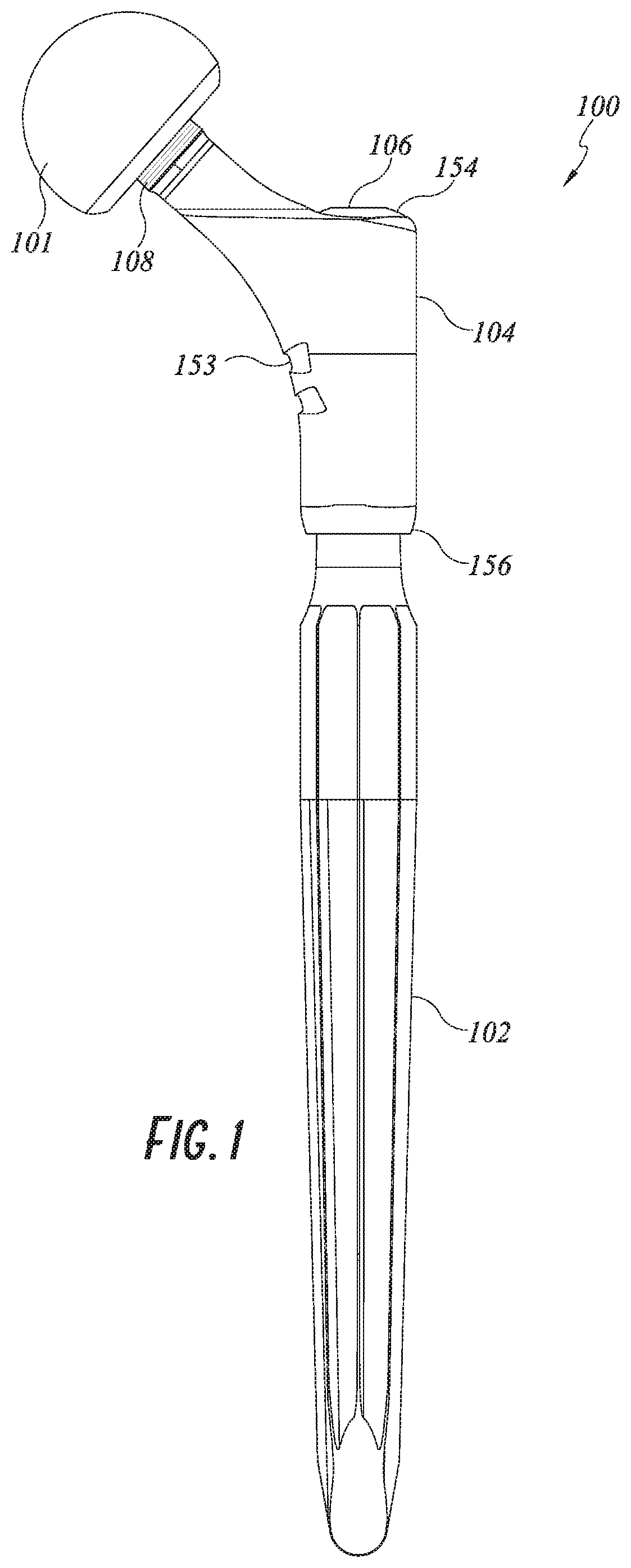
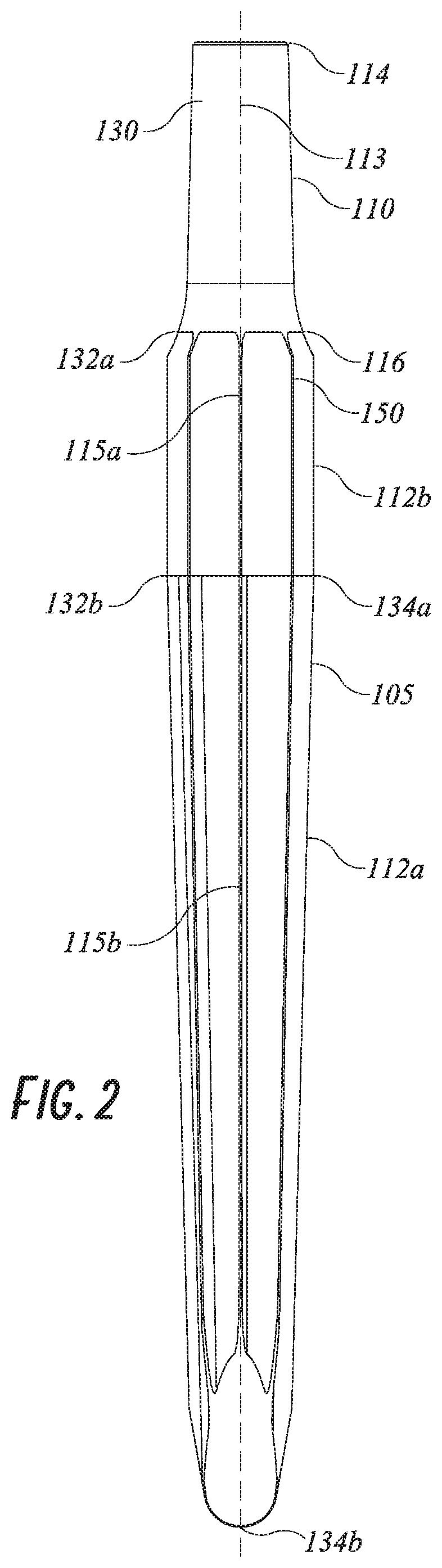
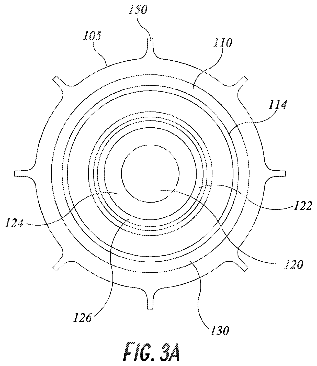
[0050]The following detailed description is directed to certain specific embodiments of the invention. However, the invention can be embodied in a multitude of different ways. It should be apparent that the aspects herein may be embodied in a wide variety of forms and that any specific structure, function, or both being disclosed herein is merely representative of one or more embodiments of the invention. An aspect disclosed herein may be implemented independently of any other aspects and that two or more of these aspects may be combined in various ways. For example, an apparatus (e.g., the illustrated embodiments a distal stem or a proximal body) may be implemented, or a method may be practiced, using any number of the aspects set forth herein. In addition, such an apparatus may be implemented or such a method may be practiced using other structure, functionality, or structure and functionality in addition to, or other than one or more of the aspects set forth herein.

[0051]FIG. 1 d...


PUM


Abstract

Hip implant systems described herein can include a distal stem, a proximal body, and a fastener. In some embodiments, the distal stem can include a cavity configured to receive the fastener when a portion of the distal stem is positioned within the proximal body. In some embodiments, the distal stem can include a threaded exterior surface configured to mate with a fastener when a portion of the distal stem is positioned within the proximal body. In some embodiments, a distal end of the distal stem can include an anterior relief configured to conform to interior surface of a femoral canal of a patient.

Description

INCORPORATION BY REFERENCE TO ANY PRIORITY APPLICATIONS[0001]Any and all applications for which a foreign or domestic priority claim is identified in the Application Data Sheet as filed with the present application are hereby incorporated by reference under 37 CFR 1.57. This application claims the benefit of U.S. Provisional Patent Application No. 62 / 462,829, filed Feb. 23, 2017, entitled “HIP IMPLANT SYSTEM,” the content of which is hereby incorporated by reference in its entirety.BACKGROUNDField[0002]This invention generally relates to prosthetic implants for both primary and revision hip applications. More specifically, this invention generally relates to systems of prosthetic implants, for example, systems that may include a stem, a proximal body, and a fastener.Description of the Related Art[0003]A damaged hip joint can cause pain and decreased mobility and may necessitate hip replacement surgery. Hip replacement surgery involves removal of at least part of a hip joint and repl...

Claims


Application Information

Patent Timeline
Patent Type & Authority Patents(United States)
IPC IPC(8): A61F2/32A61F2/36A61F2/30A61B17/84
CPCA61F2/3607A61F2/367A61F2/3609A61F2/3676A61B17/842A61F2002/30332A61F2002/30405A61F2002/30507A61F2002/30594A61F2002/30604A61F2002/30881A61F2002/30884A61F2002/3652A61F2002/3686A61F2310/00017A61F2310/00023A61F2310/00029A61F2/30734A61F2002/30495A61F2002/3647A61F2002/30433
Inventor SHALLENBERG, ADAMAXELSON, STUART L.MENEGHINI, R. MICHAELSPORER, SCOTTTAUNTON, MICHAELBROWNE, JAMES ANDREWKIM, RAYMONDEDWARDS, PAUL K.MASON, MICHAELJANKIEWICZ, JOSEPHMCBRIDE, MARK
Owner ENCORE MEDICAL L P D B A DJO SURGICAL
Why Eureka
Try Eureka