Anatomic monolithic hip implant system

Inactive Publication Date: 2014-09-11
HOWMEDICA OSTEONICS CORP
View PDF2 Cites 1 Cited by
  • Summary
  • Abstract
  • Description
  • Claims
  • Application Information

AI Technical Summary

Benefits of technology

[0008]As used herein when referring to bones or other parts of the body, the term “proximal” means close to the heart and the term “distal” means more distant from the heart. The term “inferior” means toward the feet and the term “superior” means towa

Problems solved by technology

However, a modular design has several drawbacks, for example, a large number of different parts must be provided in kit form and because of the modular d

Method used


Image

  • Anatomic monolithic hip implant system
  • Anatomic monolithic hip implant system
  • Anatomic monolithic hip implant system

Examples


Embodiment Construction

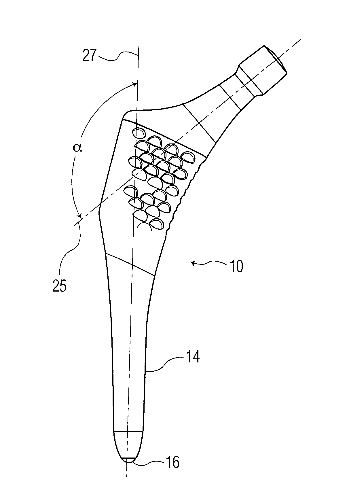
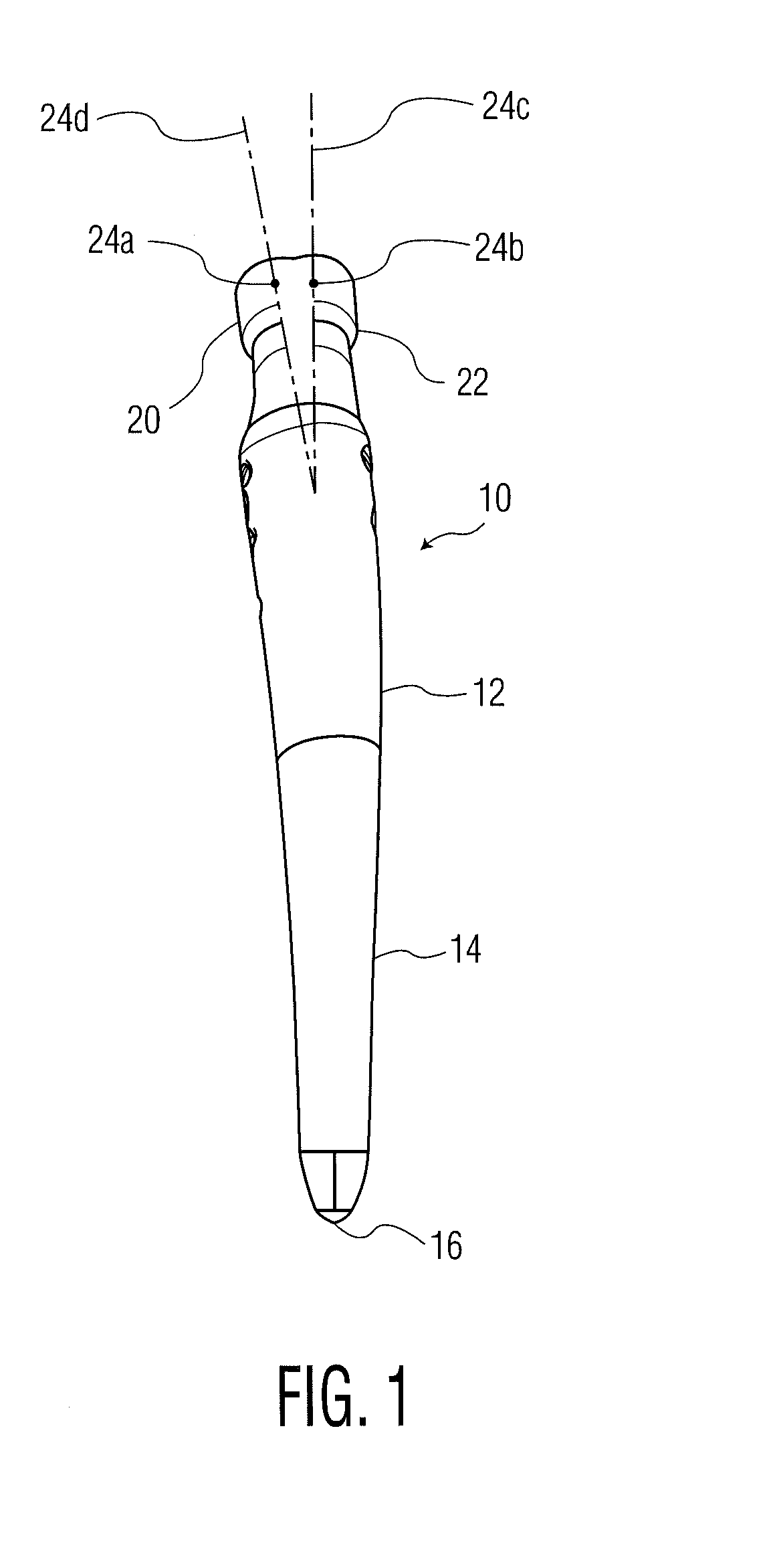
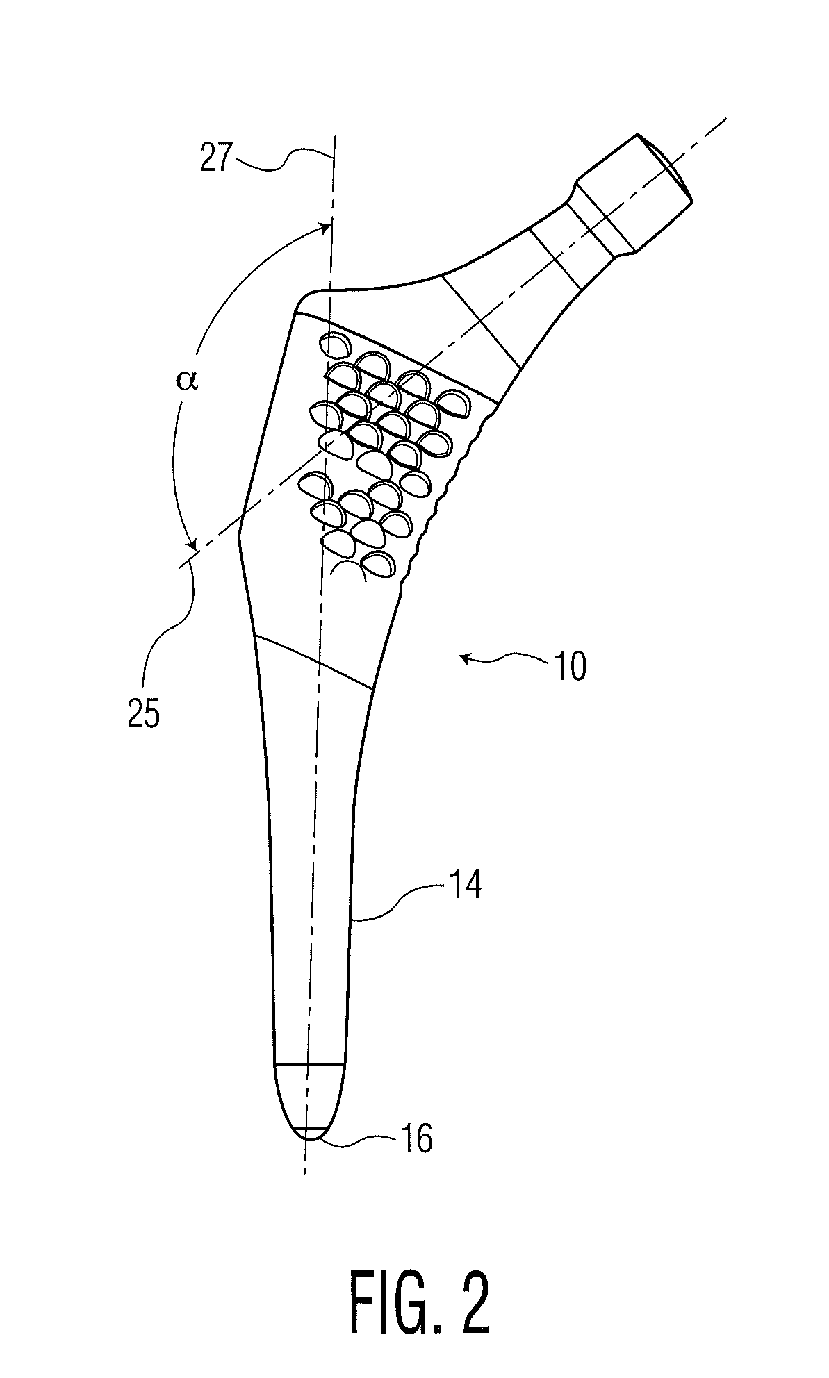
[0015]Referring to FIGS. 1 and 2A there is shown a left medium size femoral component generally denoted as 10, having a proximal stem portion 12 and distal stem portion 14 with a distal tip 16. Proximally of portion 12, there is shown a neck portion 18 with both an anteverted proximal end 20 and a neutral proximal end 22 with a tapered trunnion 24 for receiving a modular part-spherical head or ball (not shown). The tapered proximal end of the neck 24 may have a Morse taper with a centroid 24a when anteverted and a centroid 24b when neutral. Obviously, for each stem size two separate stems would be provided for both the left and right femoral implant, one having centroid 24b which is neutral in version and the other having centroid 24a which is anteverted a distance 4 to 5 mm from point 24b. Axis 24c is the axis of neck 18 in neutral and axis 24d is the axes of neck 18 when anteverted.

[0016]Thus, for each stem size, an anatomic femoral component stem would be provided for the right (...


PUM


Abstract

An anatomic prosthetic femoral implant system has a series of modular part-spherical heads and between 4 and 8 femoral component size groups. Each size group has only four components, two left and two right hip implants. One right and one left component being neutral in version and one right and one left being anteverted at an angle producing a head offset of between 4 and 5 mm from neutral. The head offset remains in this 4-5 mm range through all the size groups in the system. It has been found that a large proportion of the target patient population can be served by such a system.

Description

BACKGROUND OF THE INVENTION[0001]This invention relates to a monolithic (one-piece) femoral hip prosthesis and more particularly to a femoral hip stem component having an anatomic shape which produces a line-to-line contact with a prepared femoral medullary canal.[0002]Hip arthroplasty procedures involve the implantation of a prosthetic stem component within a femoral intramedullary canal. A ball-shaped head on the proximal end of the stem cooperates with a socket of an acetabulum to provide for articulation between the femur and the acetabulum. In order to maintain pain-free articulation of the hip joint following implantation of the stem, it is important that the stem be securely fastened in the intramedullary canal. When a press-fit or line-to-line contact is desired with the intramedullary canal, the stem contour should closely match the contour of the prepared intramedullary canal.[0003]The anatomy of the femur varies considerably from one individual to another. Version of the ...

Claims


Application Information

Patent Timeline
IPC IPC(8): A61F2/36
CPCA61F2/3662A61F2/36A61F2002/30616A61F2002/30538A61F2002/3625
Inventor GERGES, JUSTIN JOSEPHBOUCHER, FLORIANCOLLET, PASCAL
Owner HOWMEDICA OSTEONICS CORP
Why Eureka
Try Eureka