
Device, method and system for digitizing position and orientation information of hip joint implant components

a technology for positioning hip joint implants and components, applied in the field of computer-aided hip replacement surgery, can solve problems such as loss of precision

Active Publication Date: 2011-10-13
ORTHOSOFT ULC
View PDF1 Cites 3 Cited by
  • Summary
  • Abstract
  • Description
  • Claims
  • Application Information

AI Technical Summary

Benefits of technology

This approach ensures precise positioning and orientation of hip joint implants, improving the accuracy of surgical procedures by providing reliable navigation information for surgeons, such as varus / valgus angles and limb length discrepancies, thereby enhancing the success of hip replacement surgeries.

Problems solved by technology

In calculating the position of the center of rotation of the femoral implant, some precision is lost considering that the fit between the ball head and the frusto-conical connector end is unpredictable to some extent.

Method used


Image

  • Device, method and system for digitizing position and orientation information of hip joint implant components
  • Device, method and system for digitizing position and orientation information of hip joint implant components
  • Device, method and system for digitizing position and orientation information of hip joint implant components

Examples


Embodiment Construction

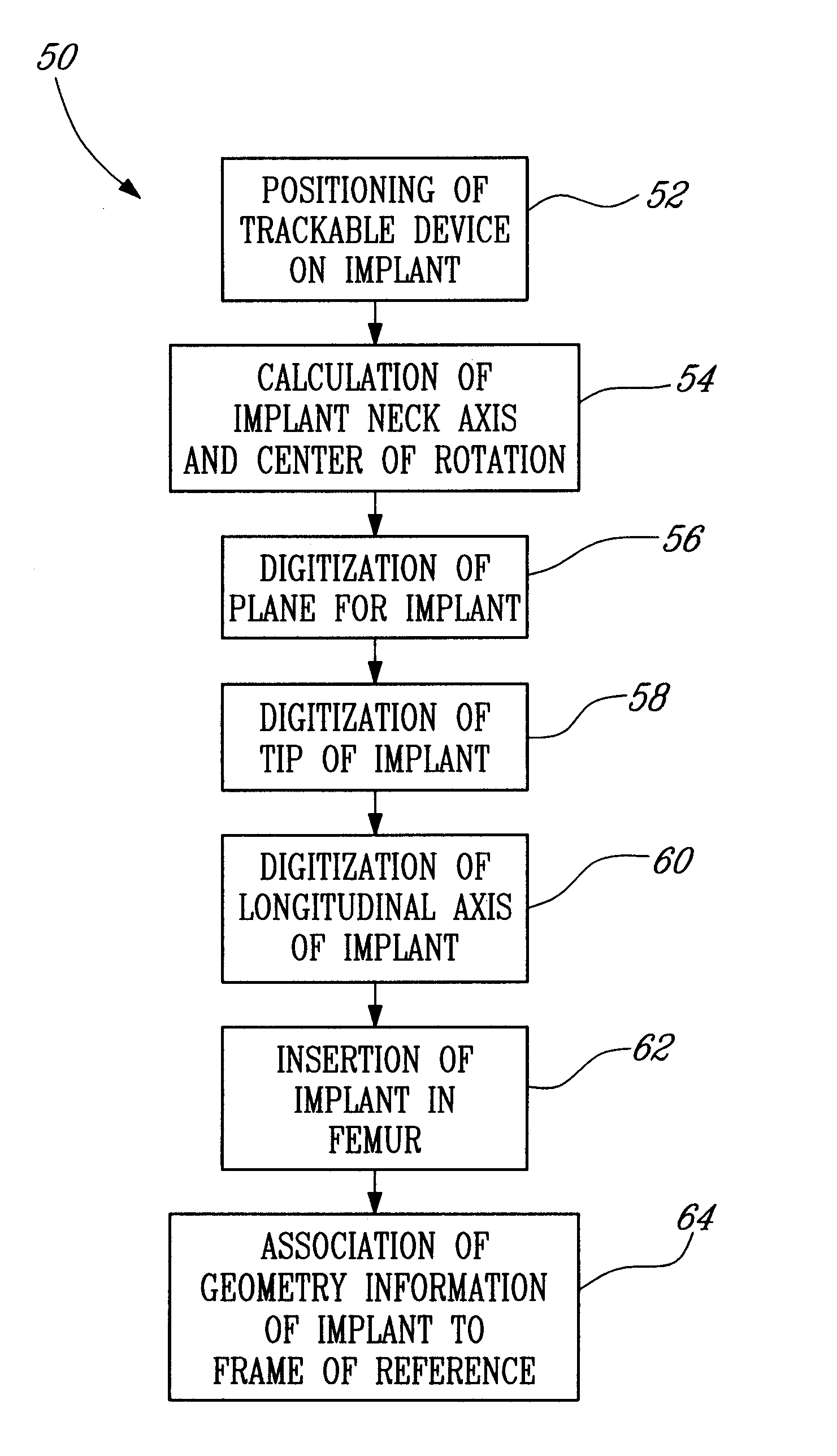
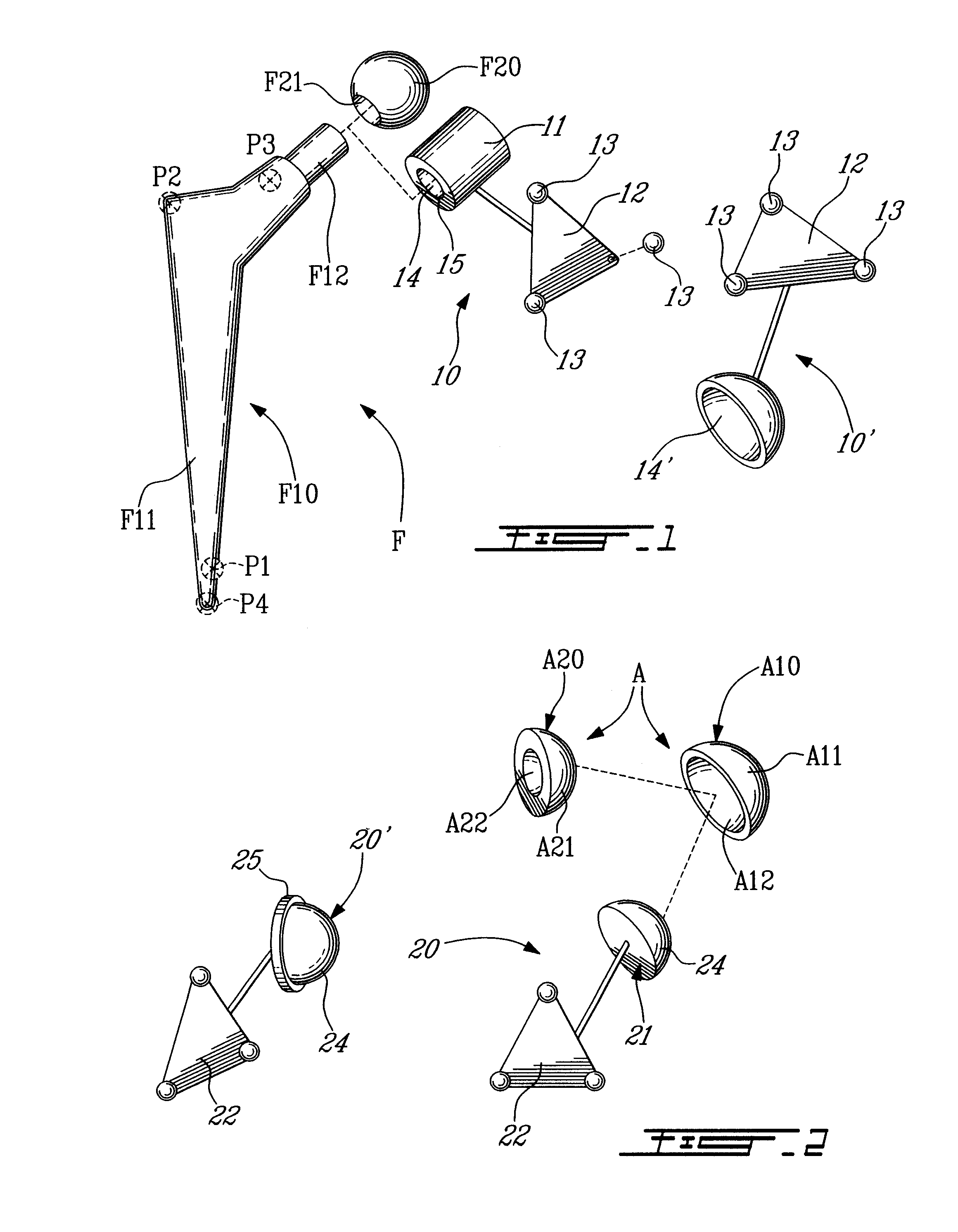
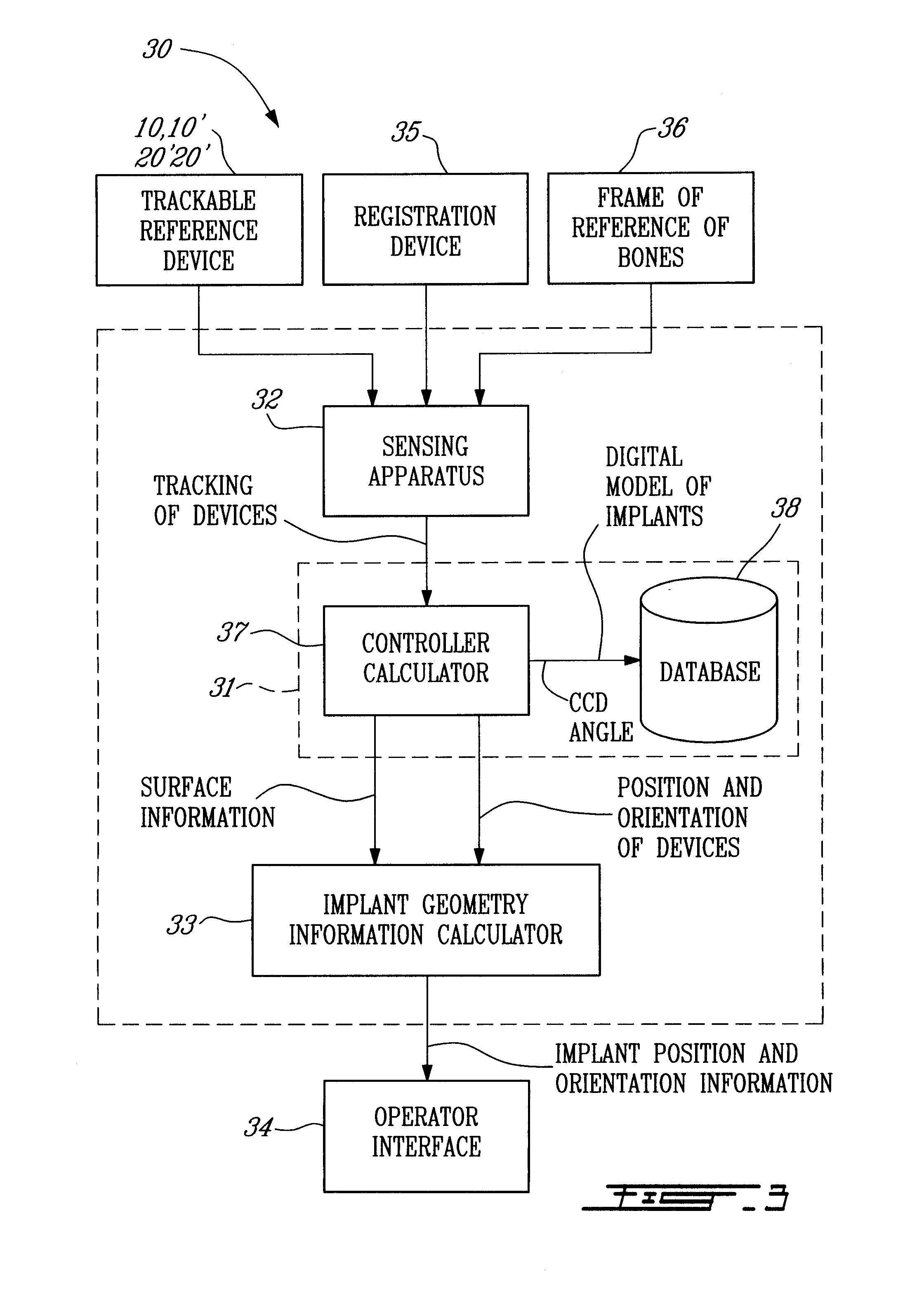
[0020]Referring to the drawings and, more particularly, to FIG. 1, a device to be used for obtaining position and orientation information for a femoral implant is generally shown at 10. A femoral implant is shown at F, and has a body F10 and a ball head F20. The body F10 has a stem portion F11, which is adapted to be received in an intramedullary canal of a resected femur (not shown). A connector end F12 projects from an end of the stem portion F11. The connector end F12 is illustrated having a frusto-conical shape, for instance having a Morse 12 / 14 taper.

[0021]The ball head F20 has a spherical outer surface, and a connector bore F21. The connector bore F21 is illustrated having a frusto-conical shape, so as to correspond to the shape of the connector end F12 of the body F10. When the body F10 is suitably received in the intramedullary canal of the femur, the ball head F20 is secured to the connector end F12, by the complementary shapes of the connector end F12 and the connector bor...


PUM


Abstract

A device (10,10′,20,20′) for digitizing a center of rotation of a hip joint implant component (A,F) with respect to a bone element in computer-assisted surgery. The device (10,10′,20,20′) comprises a detectable member (12,22) trackable for position and orientation by a computer-assisted surgery system (30). A body (11,21) is connected to the detectable member (12,22) in a known geometry. The body (11,21) has a coupling portion (14,14′,24,25) adapted to be coupled to the hip joint implant component (A,F) in a predetermined configuration. The center of rotation of the hip joint implant component (A,F) is calculable in the predetermined configuration as a function of the known geometry and of the position and orientation of the detectable member (12,22).

Description

CROSS-REFERENCE TO RELATED APPLICATIONS[0001]The present patent application is a divisional of U.S. application Ser. No. 10 / 570,630, filed on Mar. 3, 2006, which is a United States national-phase entry of International Patent Application No. PCT / CA2004 / 001638, bearing an international filing date of Sep. 7, 2004, and claiming priority on Canadian Patent Application No. 2,439,850, filed on Sep. 4, 2003.FIELD OF THE INVENTION[0002]The present invention generally relates to computer-assisted hip replacement surgery and, more particularly, to a device for positioning hip joint implant components during surgery, and to a system and method associated with the device.BACKGROUND OF THE INVENTION[0003]Computer-assisted surgery (CAS) systems provide position and orientation information in different forms throughout the operative steps, to guide the surgeon in his / her decision making. CAS systems are used for instance to assist surgeons in hip replacement surgery. In hip replacement surgery, t...

Claims


Application Information

Patent Timeline
Patent Type & Authority Applications(United States)
IPC IPC(8): G06F17/10A61B5/103A61B34/10A61F2/00A61F2/34A61F2/36A61F2/46
CPCA61F2002/3611A61B2019/505A61F2/3676A61B19/5244A61F2/367A61B19/52A61F2/4657A61F2310/00023A61B2019/5483A61B2019/508A61B2019/5272A61F2002/4631A61F2002/30332A61F2002/4658A61F2002/3625A61F2/34A61B2019/502A61B2019/566A61B2019/5255A61F2002/365A61F2002/4668A61F2310/00011A61F2310/00179A61F2002/4632A61B2019/5268A61F2/4684A61F2/36A61F2220/0033A61B2090/3983A61B2034/102A61B90/36A61B2034/2055A61B2034/2068A61B2034/2072A61B2034/256A61B34/20A61B2034/105A61B2034/108
Inventor AMIOT, LOUIS-PHILIPPEJANSEN, HERBERT ANDREFONTAINE, ISABELLEODERMATT, DANIEL
Owner ORTHOSOFT ULC
Learn More