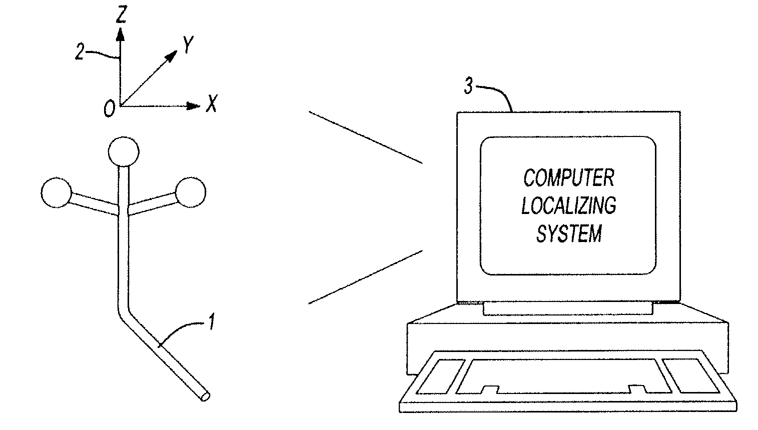
[0013]According to an aspect of the present invention there is provided a computer assisted surgical
navigation system for registering the position of prosthetic hip joint components. The system includes a first reference element applied to the pelvis that generates a first three-dimensional dynamic
reference array, which is independently registered in the system. A second reference element is applied to the femur that generates a second three-dimensional dynamic
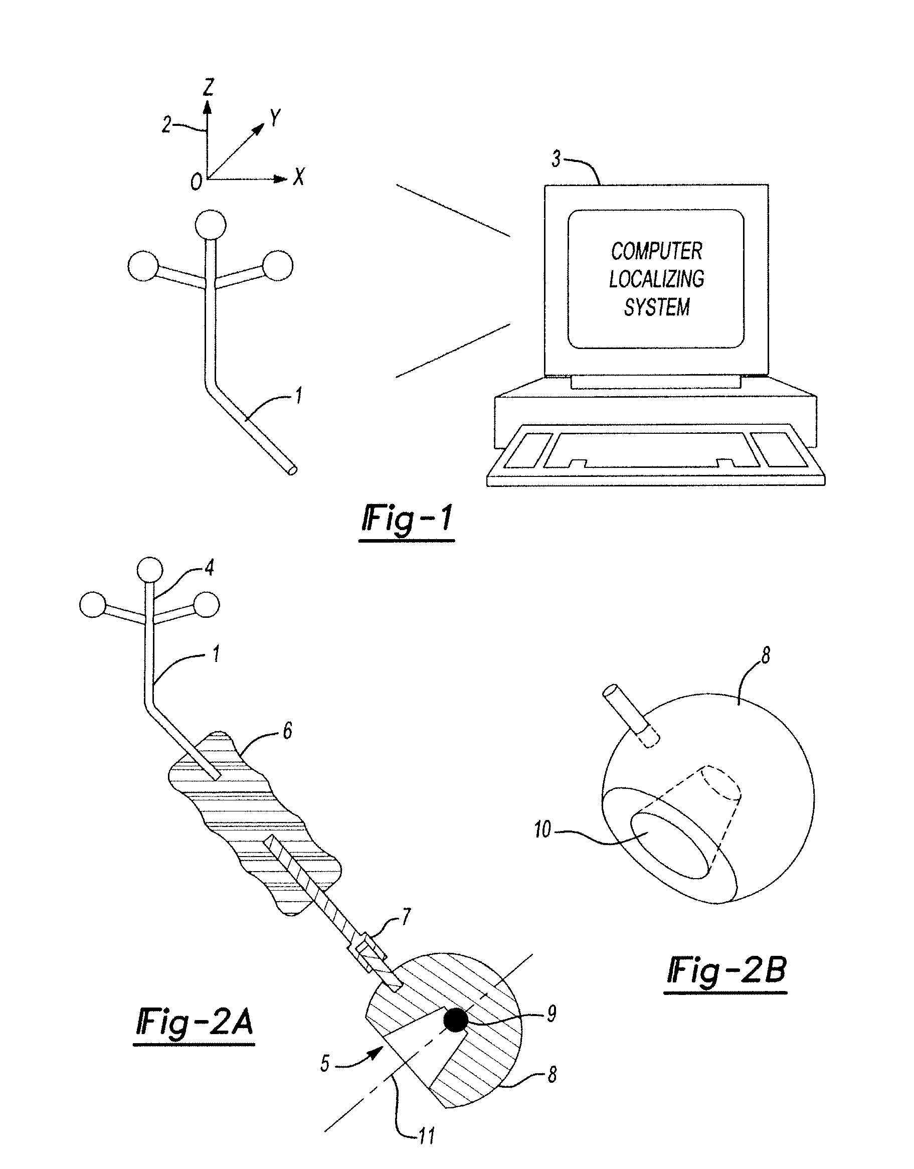
reference array, which is independently registered in the system. A three-dimensional dynamic reference point is derived from the first and second dynamic arrays and represents the native anatomical center, which is independently registered in the system. A third three-dimensional dynamic reference point represents the native anatomical center, which is derived from the first and second dynamic arrays and independently registered in the system. A tracking device generates a third three-dimensional dynamic
reference array, which is independently registered in the system. The device has a pre-determined hemispherical ball shape and dimensions that precisely articulate with an
acetabular component. The device has a further pre-determined shape and dimensions that independently and precisely articulate with a modular neck of a
femoral component, representing a prosthetic joint center that is independently registered in the system. The tracking device concurrently registers in the system the three dimensional positions of the femoral and acetabular prosthetic components, the prosthetic joint center and the native anatomical joint center, respectively. This enables the
surgical team to intraoperatively represent alterations in three dimensional location of the
leg length and offset prior to any reduction of the prosthetic joint.
[0014]According to another aspect of the present invention there is provided a method for registering the position of prosthetic hip joint components during a total
joint arthroplasty procedure. The method provides a computer assisted three-dimensional surgical
navigation system. The method includes the step of applying a first reference element to the pelvis, generating a first three-dimensional dynamic reference array and independently registering the first array in the system. Another step is applying a second reference element to the femur, generating a second three-dimensional dynamic reference array and independently registering the second array in the system. A three-dimensional dynamic reference point is derived from the first and second dynamic arrays and represents the native anatomical center, which is independently registered in the system. The method provides a tracking device with a pre-determined shape and dimensions, generating a third three-dimensional dynamic reference array representing the device and independently registering it in the system. The method precisely articulates the device independently with a correspondingly shaped and sized acetabular cup component and a neck portion of a femoral component, representing a prosthetic joint center and independently registering it in the system. The method concurrently registers the three-dimensional positions of the femoral and acetabular components, the prosthetic joint center and the native anatomical joint center, respectively, in the system. This method enables the
surgical team to intraoperatively represent alterations in three dimensional location of the
leg length and offset in the system, prior to any reduction of the prosthetic joint.
[0016]According to a preferred embodiment, a computer assisted surgical navigation system is provided for registering the position of prosthetic hip joint components. An
optical reader or camera is registered in the system. A first reference element is applied to the pelvis including an individualized arrangement of optical markers that generates a first three-dimensional dynamic reference array, which is independently registered in the system. A second reference element is applied to the femur including another individualized arrangement of optical markers that generates a second three-dimensional dynamic reference array, which is independently registered in the system. A three-dimensional dynamic reference point is derived from the first and second dynamic arrays and represents the native anatomical center, which is independently registered in the system. A tracking device discernable by the camera or reader generates a third three-dimensional dynamic reference array, which is independently registered in the system. The device has a pre-determined hemispherical shape and dimensions that precisely articulate with an acetabular cup component. The device independently has a further geometry and dimension that precisely articulate with a neck of a femoral component to represent a prosthetic joint center, which is independently registered in the system. The tracking device concurrently registers the three dimensional positions of the femoral and acetabular components, the prosthetic joint center and the native anatomical joint center, respectively, in the system. This enables the
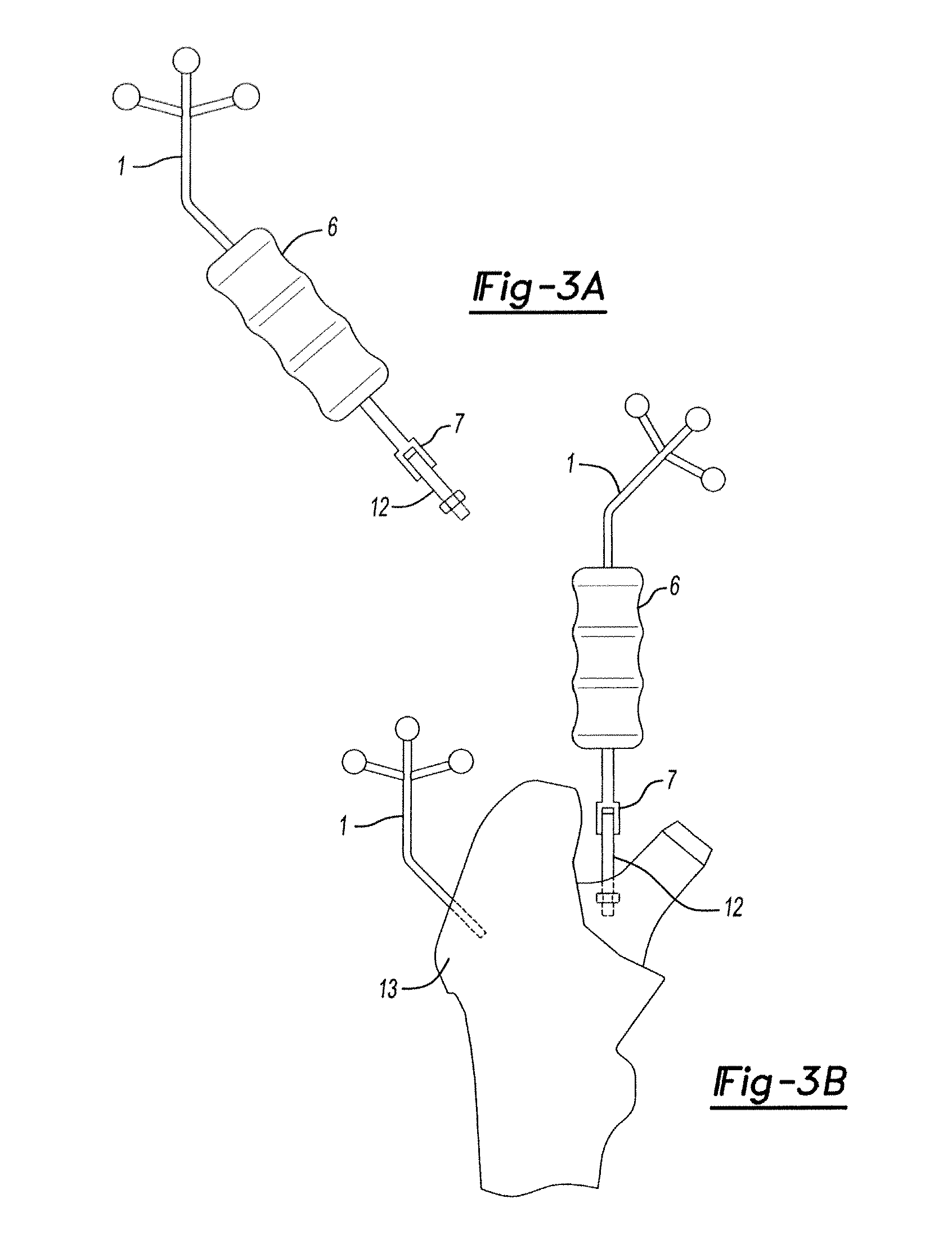
surgical team to intraoperatively represent alterations in three dimensional location of the leg length and offset prior to any reduction of the prosthetic joint. In a preferred embodiment, the system is provided with a femoral component that is a trial instrument or broach adapted for precisely articulating with the tracking device.
[0017]It is an object of the present invention to enable minimally invasive methods by providing a measuring device that can be engaged with the prosthetic targets through a limited
surgical approach. That is, the present invention creates a reference tool that allows the surgeon to position the hip
prosthetic implants using the computer to predict the final prosthetic position in relation to the various anatomical and ‘virtual’ points.
[0018]An
advantage of the present CAS system is that the positions of the anatomical features are established in a
three dimensional model, prior to any surgical manipulations such as
cutting the bone of the
proximal femur. More advantageously, with this information the preliminary prosthetic
sizing options may be rendered by the computer. By directly measuring the prosthetic hip center of the two components (the
femoral head and the acetabular cup) independently of each other, the surgeon can actually make changes or improvements in the final position.
[0019]Another
advantage of the present invention is a system that will eliminate or reduce the time needed for performing the empirical trial reductions to assess
implant position and
soft tissue tension. That is, a
surgery that is quicker, cheaper and less complex. By improving the precision of leg alignment and
ligament balancing, two of the most important factors determining long term outcome are affected.

