
Spinning controller for NMR sample tube

a spinning controller and sample tube technology, applied in the direction of magnetic measurements, instruments, measurement devices, etc., can solve the problems of deteriorating the responsiveness of the feedback control, local variations in the spinning rate cannot be detected, and the accuracy of the spinning rate is deteriorated, so as to improve the accuracy, improve the reliability of the control, and eliminate or reduce the effect of spinning measurement errors

Active Publication Date: 2017-10-03
JEOL LTD
View PDF9 Cites 4 Cited by
  • Summary
  • Abstract
  • Description
  • Claims
  • Application Information

AI Technical Summary

Benefits of technology

This approach enhances the accuracy of spinning rate measurement and control, allowing for precise control of the sample tube's spinning, reducing measurement errors, and improving the responsiveness of the feedback control system.

Problems solved by technology

The aforementioned errors in time deteriorate the accuracy at which the spinning rate is measured.
This deteriorates the responsiveness of the feedback control.
Furthermore, local variations in spinning rate cannot be detected.
Consequently, feedback control cannot be provided in response to the variations.

Method used


Image

  • Spinning controller for NMR sample tube
  • Spinning controller for NMR sample tube
  • Spinning controller for NMR sample tube

Examples


Embodiment Construction

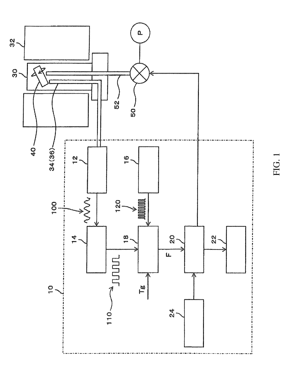
[0029]Referring to FIG. 1, there is shown an NMR measurement system including a spinning controller associated with one embodiment of the present invention, the controller being used for an NMR sample tube. In the present embodiment, the NMR measurement system performs NMR measurements on solid samples. At this time, the very thin sample tube is spun at ultrahigh speeds. The NMR sample tube, 40, is installed in the head of an NMR probe 30. The sample tube 40 is inserted in a bore 32 formed in a static magnetic field generator together with the NMR probe 30. A sample tube spinner (not shown) for spinning the sample tube 40 is installed in the head of the NMR probe 30. An NMR detection circuit (not shown) is installed in the head of the NMR probe 30 and has a transmit / receive coil for generating an RF magnetic field and detecting an NMR signal emanating from a nuclide to be observed. The NMR measurement system further includes transmit and receive signal processing circuitry and a spe...


PUM


Abstract

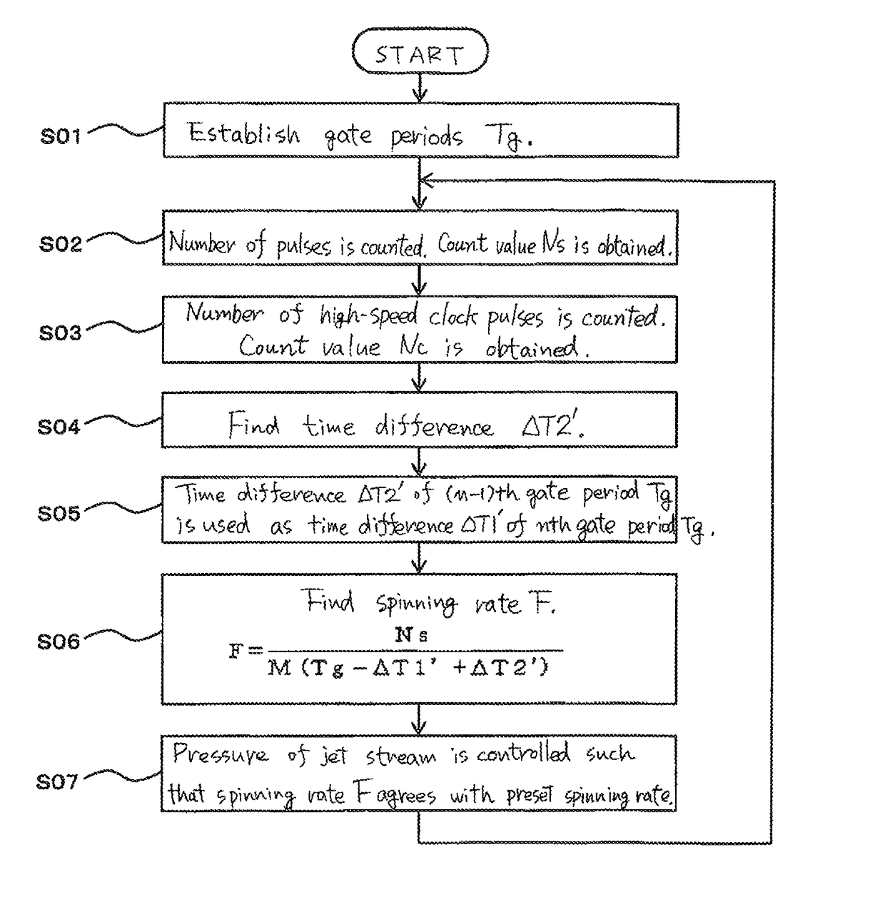
A spinning controller has an arithmetic unit (18) and a controller (20). The arithmetic unit (18) establishes gate periods Tg for a pulse sequence signal (110) produced concomitantly with spinning of a sample tube (40) and obtains a count value (Ns) by counting the number of pulses falling within each gate period Tg. The arithmetic unit (18) has functions of finding differences in time from each gate period Tg to the pulse sequence signal (110) occurring around the starting point and ending point of each gate period Tg by making use of a high-speed clock signal (120) and of correcting the duration of the gate period Tg, based on the differences in time.

Description

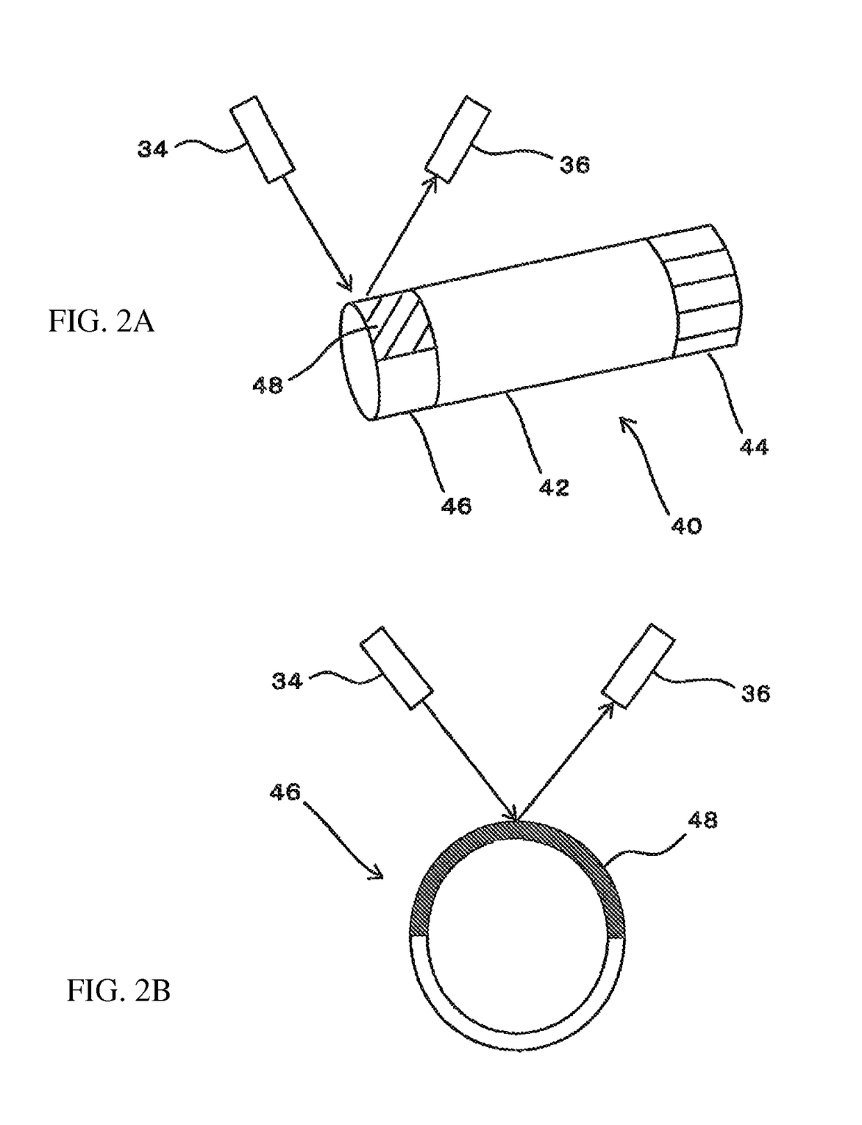
BACKGROUND OF THE INVENTION[0001]Field of the Invention[0002]The present invention relates to a controller for controlling the spinning of a sample tube used in NMR measurements.[0003]Description of Related Art[0004]In some NMR (nuclear magnetic resonance) measurements, a sample tube holding a sample therein is spun. For example, in solid-state NMR measurements, a sample tube holding a solid sample therein is spun at high speed while tilted at a given angle (magic angle) with respect to the direction of a static magnetic field. Under this condition, a transmit / receive coil surrounding the sample tube generates an RF magnetic field. The resulting NMR signal is detected by the transmit / receive coil.[0005]In the above-described NMR measurements, it is necessary to measure the spinning rate of the sample tube. For example, JP-A-3-229183 discloses an apparatus for measuring the spinning rate of an NMR sample tube. A reflecting plate is mounted on the surface of the sample tube. Light is ...

Claims


Application Information

Patent Timeline
Patent Type & Authority Patents(United States)
IPC IPC(8): G01R33/30
CPCG01R33/307
Inventor OZAKU, TOMIONISHIYAMA, YUSUKE
Owner JEOL LTD
Learn More