Apparatus for digitizing intramedullary canal and method

a technology for intramedullary canals and apparatuses, applied in the field of hip replacement surgery, can solve the problems of inconvenient use of ct, ct using x-rays, and known health hazards

Inactive Publication Date: 2005-01-27
ORTHOSOFT
View PDF25 Cites 100 Cited by
  • Summary
  • Abstract
  • Description
  • Claims
  • Application Information

AI Technical Summary

Benefits of technology

It is a further aim of the present invention to provide a novel method for guiding an operator in inserting implants in hip joint replacement with compu...

Problems solved by technology

There are inconveniences to the use of CT.
Cost saving issues are involved in the logistic simplif...

Method used


Image

  • Apparatus for digitizing intramedullary canal and method
  • Apparatus for digitizing intramedullary canal and method
  • Apparatus for digitizing intramedullary canal and method

Examples


Embodiment Construction

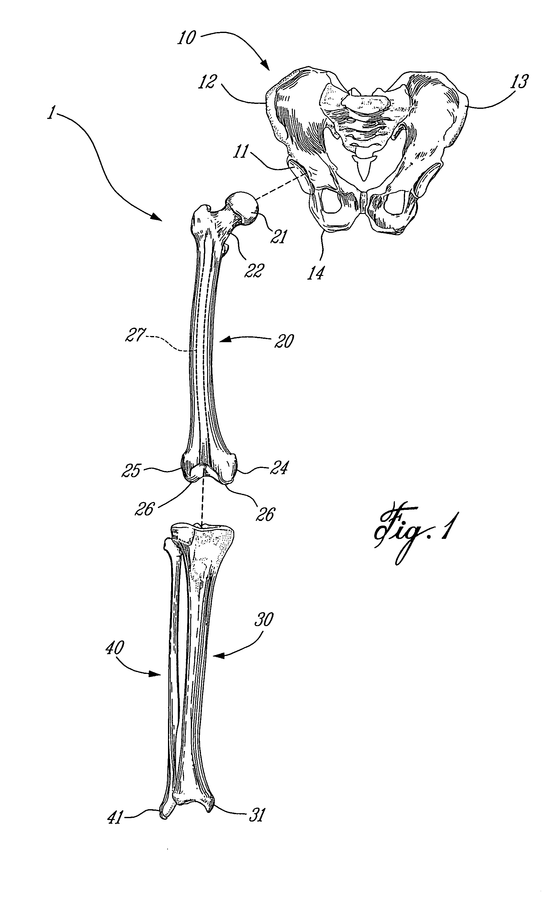
According to the drawings, and more particularly to FIG. 1, bones of the leg that will be involved in the hip replacement surgery of the present invention are generally shown at 1. FIG. 1 is provided as reference for the description of the steps of the hip replacement surgery method described herein. The bones are the pelvis 10, the femur 20, the tibia 30 and the fibula 40. Hereinafter, parts of these bones will each be referenced by numerals from the same numeric decade. For instance, parts of the pelvis (e.g., the acetabulum 11) will bear reference numerals between 11 and 19.

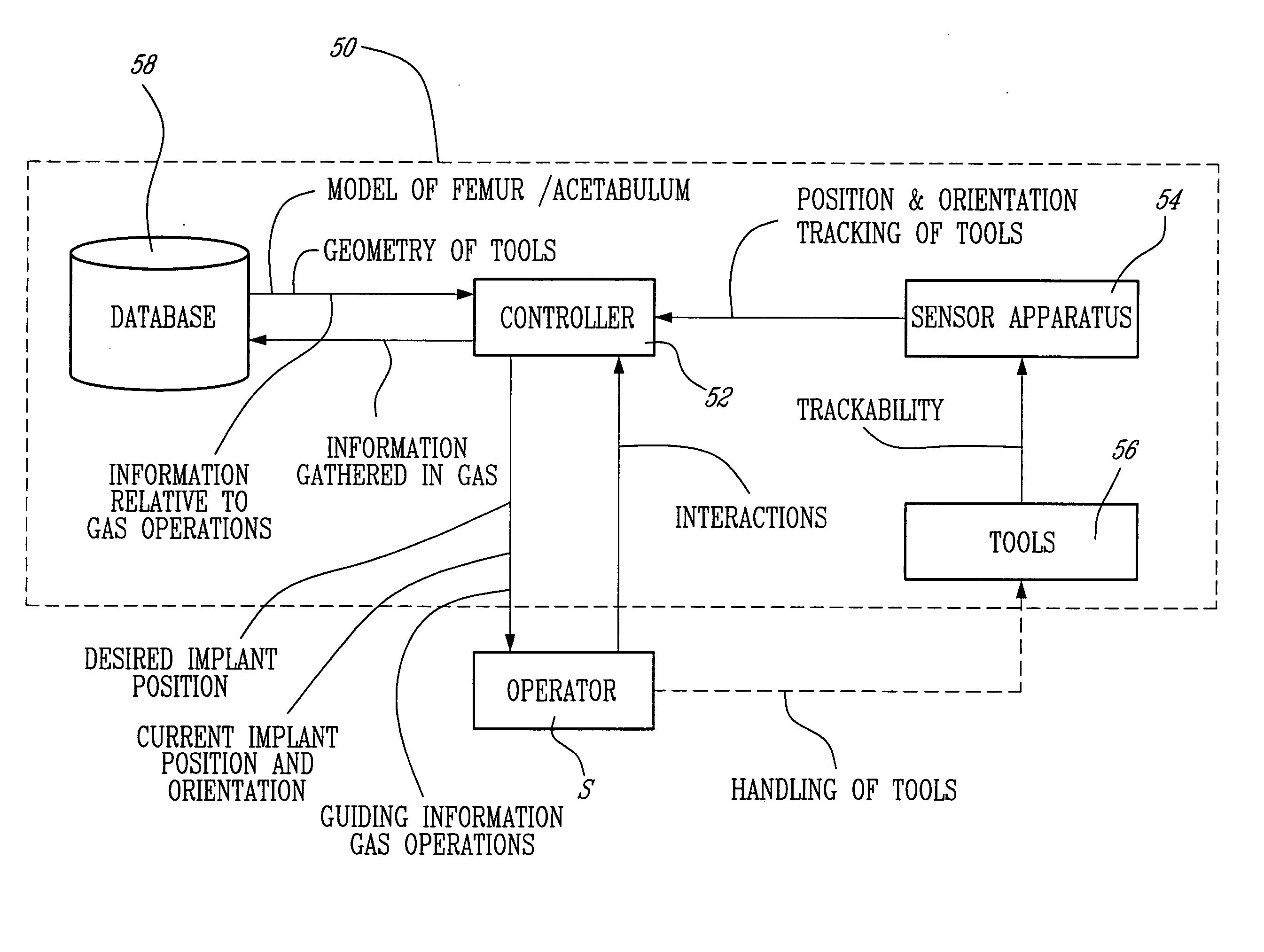
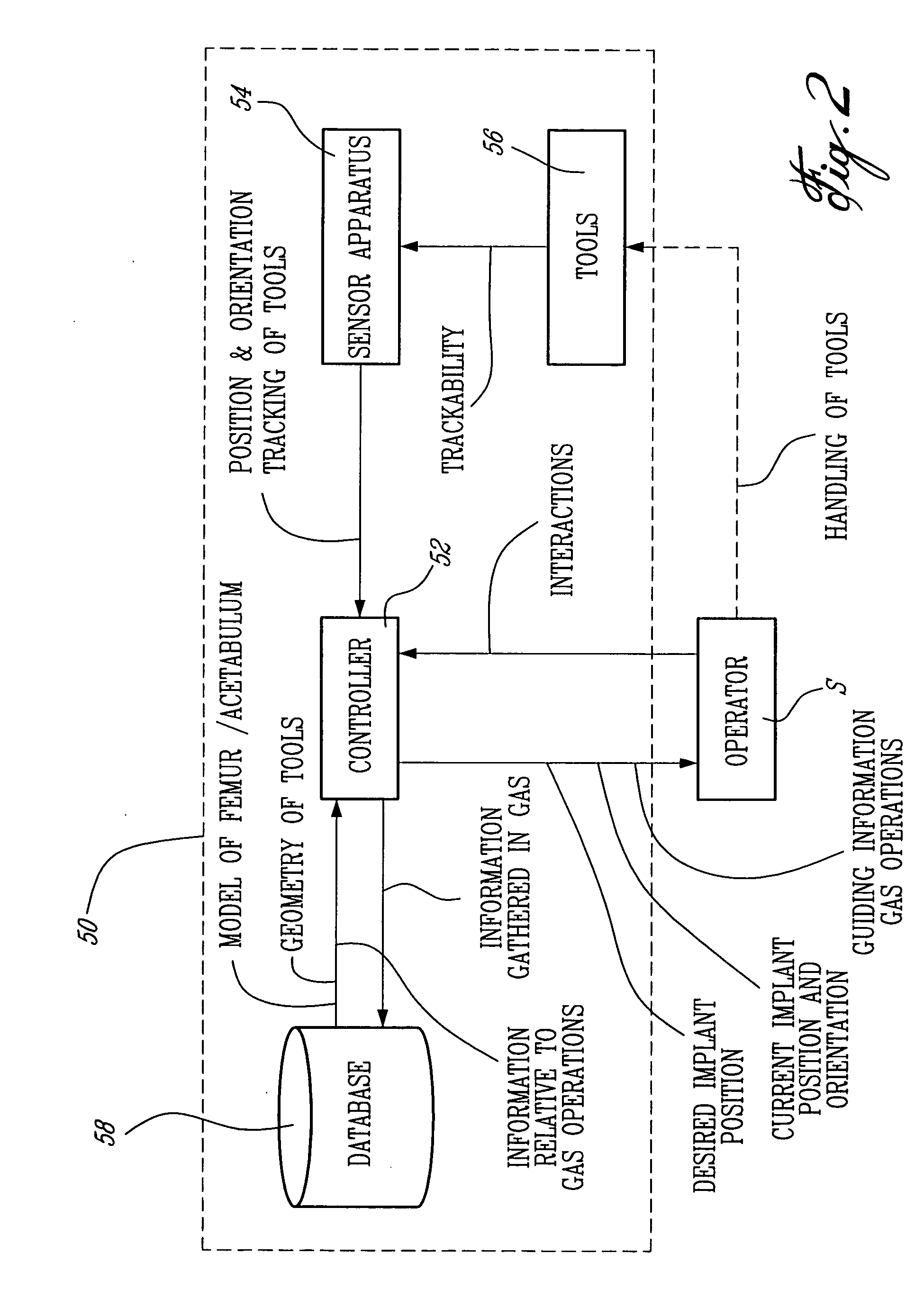
Referring to FIG. 2, a computer-assisted surgery system is generally shown at 50 (hereinafter CAS system 50) and generally consists of a CAS controller 52 connected to sensor apparatus 54. The sensor apparatus 54 tracks for position and orientation tools 56, to be described in detail with the description of the hip replacement surgery method of the present invention. The controller 52 is typically a PC unit...


PUM


Abstract

An apparatus for obtaining an axis of an intramedullary canal of an exposed bone with a position tracking system in computer-assisted surgery, comprising a detectable device trackable in space for position and orientation. A stem portion is secured to the detectable device so as to be tracked for position and orientation. The stem portion has a leading end insertable in an intramedullary canal of the bone through an opening in the bone, and is adapted to be handled by a following end thereof. A tip portion is provided at the leading end of the stem portion. The tip portion is positionable in a determined way with respect to a surface of the intramedullary canal, such that reference points with respect to the intramedullary canal are calculable as a function of the position and orientation of the detectable device. The reference points are related to define an axis of the intramedullary canal. A method is provided for digitizing the intramedullary canal axis.

Description

FIELD OF THE INVENTION The present invention generally relates to computer-assisted hip replacement surgery and, more precisely, to hip replacement surgery with minimal preoperative procedures. BACKGROUND OF THE INVENTION Total hip replacement surgery involves the introduction of an artificial hip joint in a patient. The artificial hip joint typically consists of a pelvic implant and a femoral implant. The pelvic implant is a cup received in the acetabulum. The femoral implant consists of a spherical portion received at an end of a longitudinal implant portion. The longitudinal implant portion is introduced into the intramedullary canal of the resected femur, with the spherical portion being generally centered with respect to the previous position of the femoral head. Therefore, the femoral head (i.e., spherical portion of the femoral implant) and the cup (i.e., pelvic implant) coact to create the artificial hip joint. Different output values are of concern in hip replacement sur...

Claims


Application Information

Patent Timeline
IPC IPC(8): A61B5/103A61B17/15A61B17/16A61B17/17A61B19/00A61F2/30A61F2/34A61F2/36A61F2/46G09B23/28G09B23/30
CPCA61B5/064A61B5/6878A61B5/4528A61B17/15A61B17/1666A61B17/1703A61B17/1717A61B17/1735A61B17/1746A61B17/175A61B19/22A61B19/50A61B19/52A61B19/5244A61B19/56A61B2019/462A61B2019/502A61B2019/505A61B2019/508A61B2019/5255A61B2019/5268A61B2019/5272A61B2019/5287A61B2019/5483A61B2019/562A61B2019/566A61F2/34A61F2/4607A61F2/4609A61F2/4657A61F2002/30952A61F2002/3611A61F2002/4632A61F2002/4658A61F2002/4668A61F2002/4681A61F2002/4697G09B23/28G09B23/30A61B5/103A61B2090/3983A61B2034/102A61B90/36A61B2034/2055A61B2034/2068A61B2034/2072A61B2090/363A61B2034/256A61B34/20A61B34/70A61B34/25A61B2090/062A61B2034/105A61B2034/108A61B2034/252A61B34/10A61F2002/4696A61B2034/104A61B2034/107A61F2/32
Inventor JANSEN, HERBERT ANDREAMIOT, LOUIS-PHILIPPECOSSETTE, SEBASTIENJUTRAS, SEBASTIENPELLETIER, BENOIT
Owner ORTHOSOFT
Why Eureka
Try Eureka