Bone tracking with a gyroscope sensor in computer-assisted surgery

Active Publication Date: 2012-02-02
ORTHOSOFT ULC
View PDF6 Cites 79 Cited by
  • Summary
  • Abstract
  • Description
  • Claims
  • Application Information

AI Technical Summary

Benefits of technology

[0005]It is therefore an aim of the present disclosure to provide novel metho

Problems solved by technology

However, the orientation of the sensor relative to the femoral mechanical axis is more complex, as one of the anatomical landmarks defining the axis, the femoral head, is hidden inside the hip.
However, in a MEMS system, sensors do not automatically provide 6DOF.
The 6DOF can be retrieved by integrati

Method used


Image

  • Bone tracking with a gyroscope sensor in computer-assisted surgery
  • Bone tracking with a gyroscope sensor in computer-assisted surgery
  • Bone tracking with a gyroscope sensor in computer-assisted surgery

Examples


Embodiment Construction

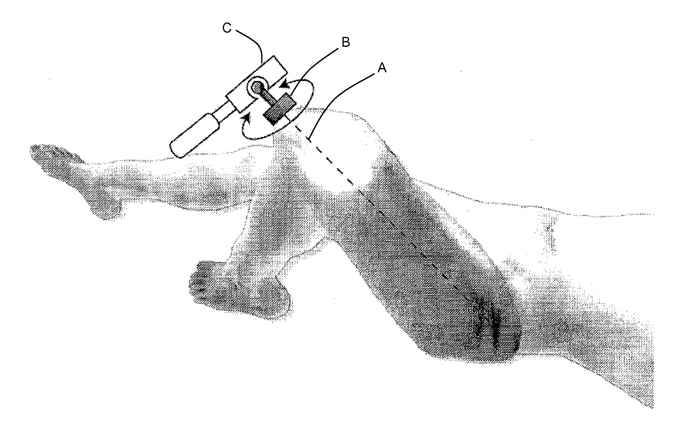
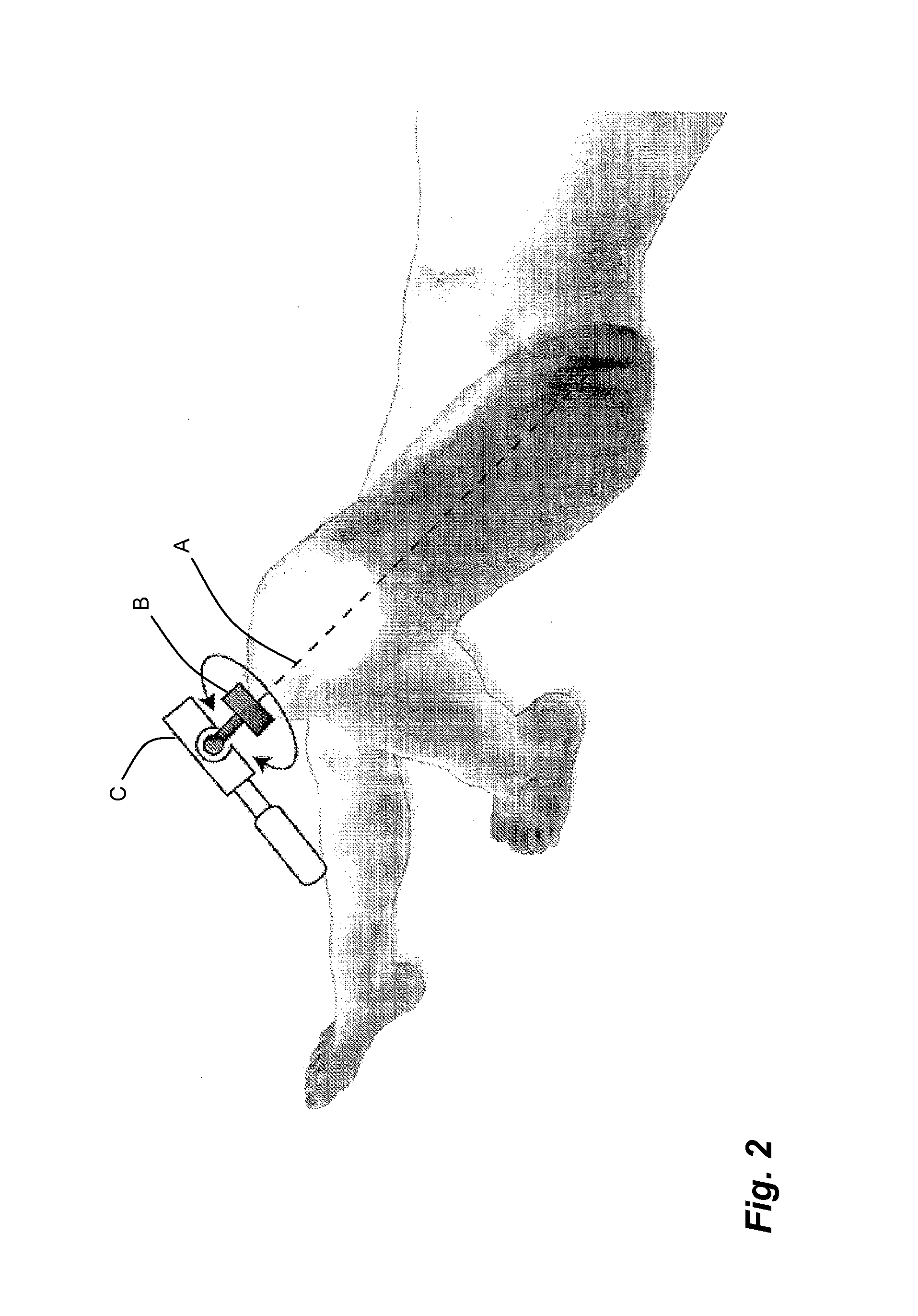
[0013]A gyroscope is a sensor which measures the instantaneous rotational velocity about an axis. If several gyroscope sensors are combined in a specific arrangement, a three-axis gyroscope sensor unit measuring the rotational velocity in x, y and z of a body is obtained. One property of gyroscopes is that if a three-axis gyroscope sensor unit rotates about a fixed axis, its output in x, y and z will be proportional to a direction of the rotation axis in the sensor coordinate system. The output represents a simultaneous rotation in x, y and z about a unit vector. Accordingly, three-axis gyroscope sensor units may be used to track axes of bones in computer-assisted surgery.

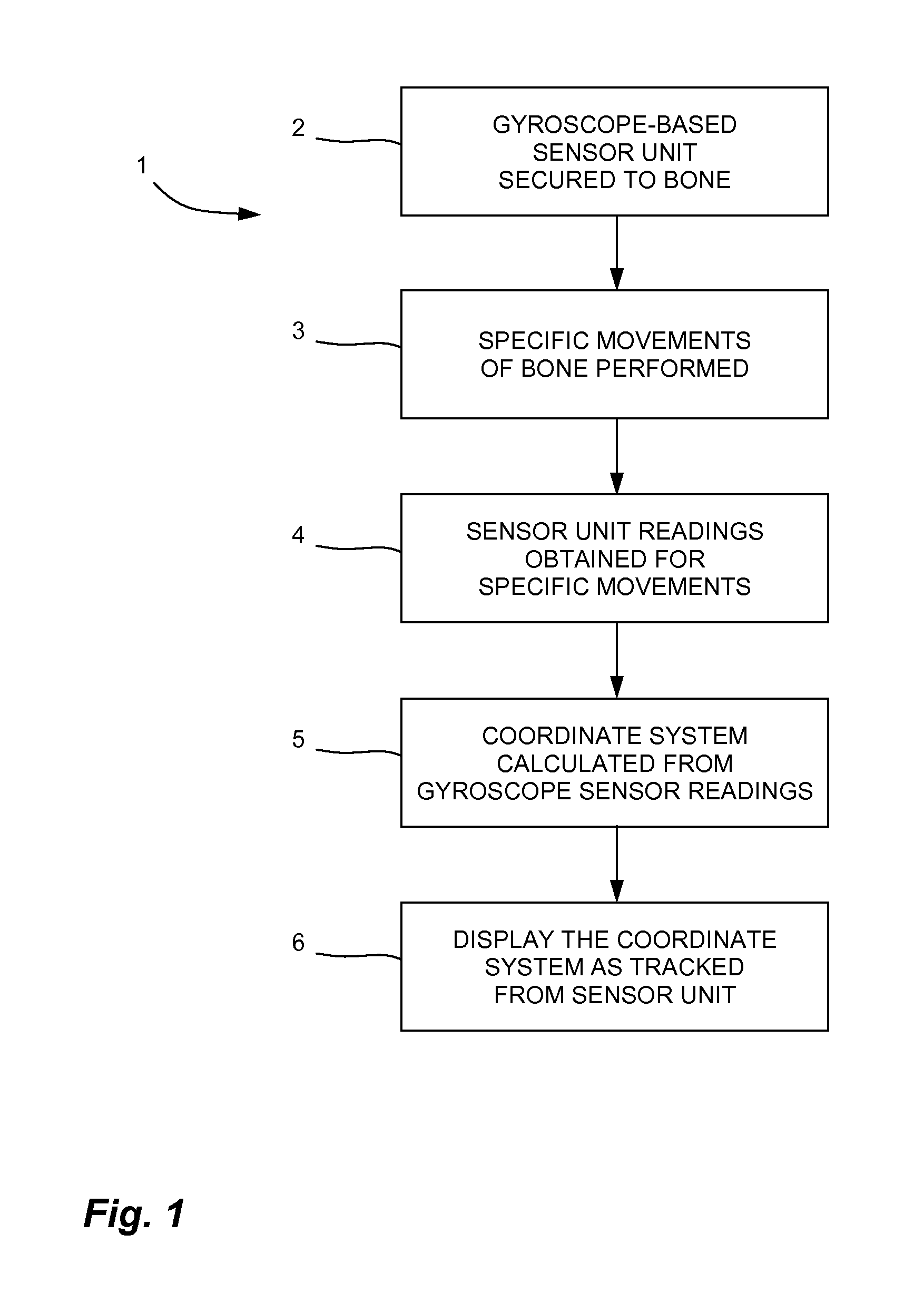
[0014]Referring to the drawings and more specifically to FIG. 1, there is illustrated a method 1 for tracking a bone in computer-assisted surgery. For clarity, the method 1 is described in an application related to the tracking of a femur. However, the method 1 can be used with some other bones and body parts, as w...


PUM


Abstract

A system tracks an object in computer-assisted surgery. The system comprises a sensor unit secured to the femur. Gyroscopes on the sensor unit produce readings related to orientation data about three axes of rotation. A tracking unit receives the gyroscope readings. An axis calibrator on the tracking unit comprises a calculator for adding at least part of the gyroscope readings for specific movements of the object about a desired axis. An axis normalizer on the tracking unit determines an orientation of the desired axis with respect to the sensor unit from the added gyroscope readings. A tracking processor tracks the desired axis from the gyroscope readings. An interface displays orientation data for the object from a tracking of the desired axis. A method for tracking an object with a gyroscope sensor unit is also provided.

Description

FIELD OF THE APPLICATION[0001]The present application relates to tracking body parts such as bones in computer-assisted orthopedic surgery using gyroscopes and other microelectromechanical sensors (MEMS).BACKGROUND OF THE ART[0002]One of the essential steps in navigating a bone with MEMS sensors is to initially locate the bone relative to the sensors. For the femur, the orientation of the sensor relative to the lateral axis can be constrained mechanically, for instance, with claws inserted under the posterior condyles so that the sensor lateral axis is aligned with the lateral axis of the bone. However, the orientation of the sensor relative to the femoral mechanical axis is more complex, as one of the anatomical landmarks defining the axis, the femoral head, is hidden inside the hip.[0003]In an optical navigation system, the femoral head is located by moving the femur and, assuming the pelvis is stable, finding the fixed pivot point around which the bone rotates. This relies on the...

Claims


Application Information

Patent Timeline
IPC IPC(8): A61B5/11G01M19/00
CPCA61B19/5244A61B2019/5483A61B2019/5248A61B34/20A61B2034/2048A61B2090/3983
Inventor AMIOT, LOUIS-PHILIPPEZUHARS, JOELPROULX, CATHERINEVALIN, MYNAMNGUYEN, TINPELLETIER, BENOITDUVAL, KARINE DUVALRICHARD, ALAINKIBLAWI, RULABOUTIN, YANNICK
Owner ORTHOSOFT ULC
Why Eureka
Try Eureka