Laser range finder closed-loop pointing technology of relative navigation, attitude determination, pointing and tracking for spacecraft rendezvous
a technology of spacecraft and relative navigation, applied in the field of electronic control systems for orbital rendezvous of spacecraft, can solve the problems of misalignment of instruments, noise pollution, and inability to accurately determine the position of spacecraft, and achieve the effect of avoiding noise pollution, avoiding interference with the navigation process, and improving the accuracy of the navigation process
- Summary
- Abstract
- Description
- Claims
- Application Information
AI Technical Summary
Benefits of technology
Problems solved by technology
Method used
Image
Examples
example scenario 1
Observability of Range from Angle Measurements and Effects of Measurement Interruptions
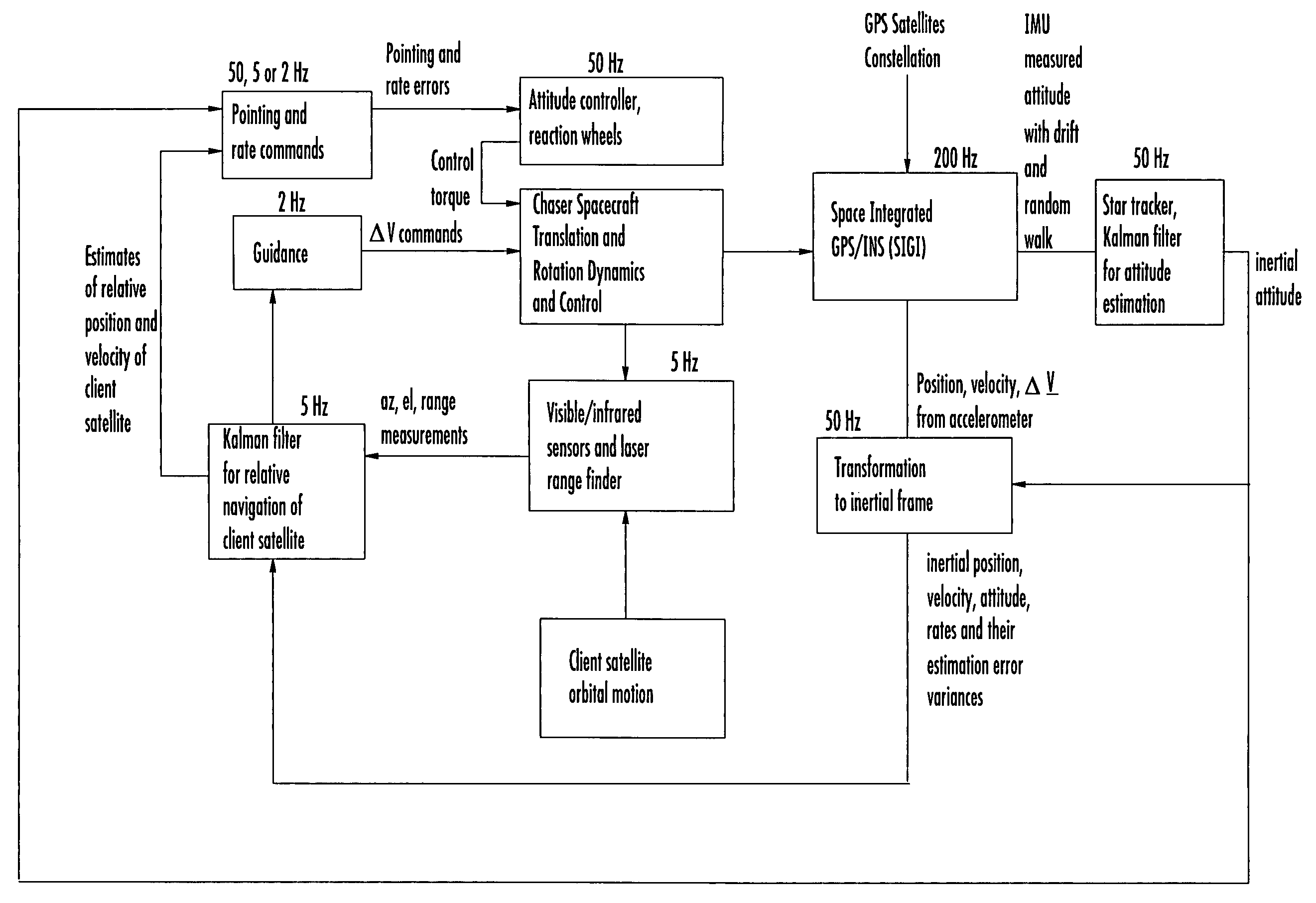
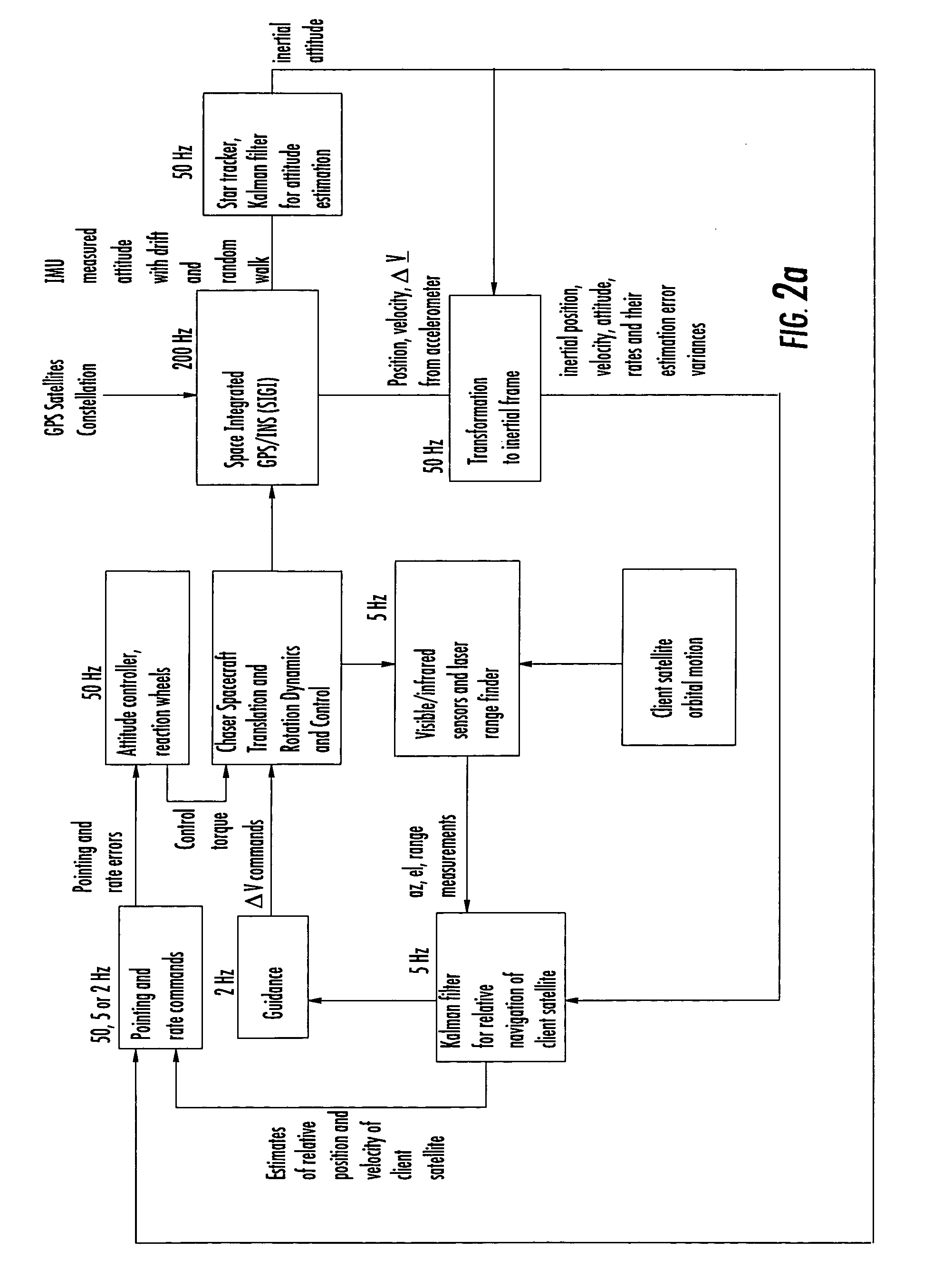
FIG. 6 illustrates a nominal scenario of a far-field rendezvous starting from ˜200 km behind and 8 km below a target satellite and the associated timeline. Specifically, the chaser starts at a relative position of [−200 0 8]T km in the LVLH- frame at t=0 with a relative velocity {dot over (x)}=3ωorb Z in the LVLH frame so that the chaser drifts at a constant altitude towards the target satellite until it reaches the coordinates [−28 0 8] km from the target where {dot over (y)}=0, {dot over (z)}=0. With a suitable increment ΔV at this location, the chaser is navigated to −6 km behind the target at zero relative altitude, and then to −1 km to +0.12 km with additional ΔVs, each after a transit period sufficiently different from the singular transit periods discussed in Ref. 12. The chaser attitude determination and control system are not simulated in this scenario. For initial conditions in the simu...
example scenario 2
Laser Range Finder Pointing
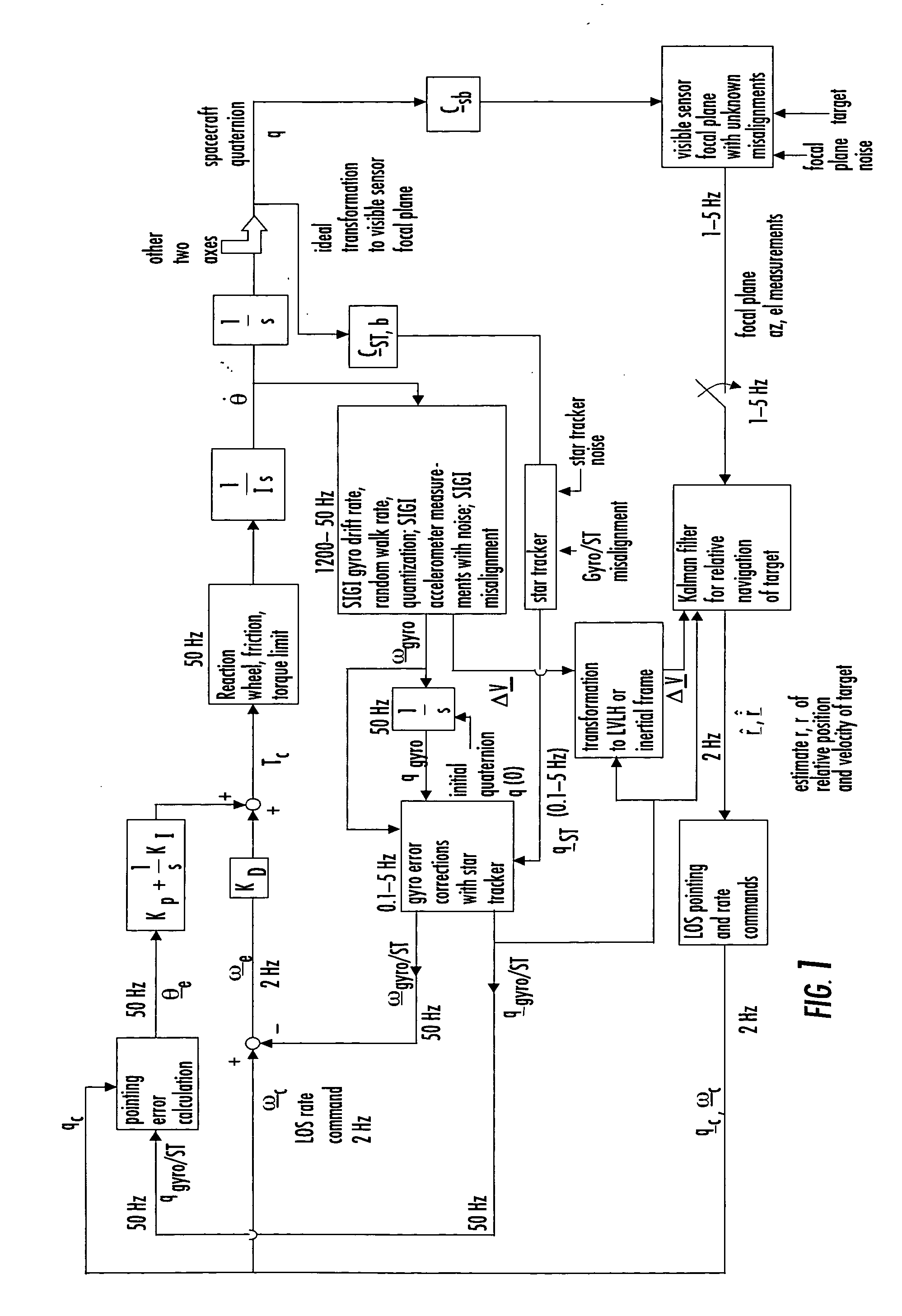
In this section, attitude determination errors arising from gyros and star tracker noises as filtered by the analytic steady-state six-state Kalman filter of one embodiment of the present invention are illustrated. Table 2 records the noise parameters of a SIGI gyro and a selected star tracker. The star tracker noise about its focal plane axes, 35 μrad, (1σ), is one-eighth of the noise about its boresight axis (280 μrad, 1σ). The three nondimensional parameters Se, Sv and Su corresponding to the gyro errors and star tracker noise about the focal plane axes for different star tracker measurement intervals are also presented in Table 2.
TABLE 2Comparison of SIGI Gyro and CT-633 Star Tracker NoisesGyro Noise ParametersBias (drift rate)0.02 μrad / sRate of change of bias (σu)4.0 e-12 rad / s3 / 2Random walk rate (σv)0.75 μrad / s1 / 2Quantization as white noise (σe) (readout noise, electronic noise)1.6 (=5.4 / 12) μradStar tracker noise σstFocal plane axis (1σ per ...
example scenario 3
Laser Rangefinder Pointing Accuracy with Sensor Misalignments
Since the LRF pointing is achieved by feeding back the visible sensor angle measurements, it is reasonable to expect reduced sensitivity of pointing accuracy to a misalignment between visible sensor, gyros and star tracker.
FIGS. 19a and 19b illustrate relative navigation and attitude controls working together to effect laser rangefinder pointing in the presence of both gyros and a star tracker independently misaligned with respect to the visible sensor frame, while the visible sensor and the laser rangefinder are collimated perfectly or near perfectly. The gyro frame is assumed to be orthogonal but misaligned by 2 millirad about each axis in one example and 5 millirad in the other example. Denoting a misalignment angle vector as δθma, the transformation matrix from the perfectly aligned frame to the imperfectly aligned but orthogonal frame is given by [1−δθmax]. In the two examples, the star tracker, in comparison to th...
PUM
 Abstract
Description
Claims
Application Information
 - R&D
- Intellectual Property
- Life Sciences
- Materials
- Tech Scout
- Unparalleled Data Quality
- Higher Quality Content
- 60% Fewer Hallucinations
Browse by: Latest US Patents, China's latest patents, Technical Efficacy Thesaurus, Application Domain, Technology Topic, Popular Technical Reports.
© 2025 PatSnap. All rights reserved.Legal|Privacy policy|Modern Slavery Act Transparency Statement|Sitemap|About US| Contact US: help@patsnap.com


