Selective Per-Cycle Masking Of Scan Chains For System Level Test

a scan chain and cycle masking technology, applied in the field of masking unknown states during the built-in self-test of integrated circuits, to achieve the effect of high observability of scan cells and increased masking efficiency

Active Publication Date: 2009-12-03
SIEMENS PROD LIFECYCLE MANAGEMENT SOFTWARE INC
View PDF18 Cites 21 Cited by
  • Summary
  • Abstract
  • Description
  • Claims
  • Application Information

AI Technical Summary

Benefits of technology

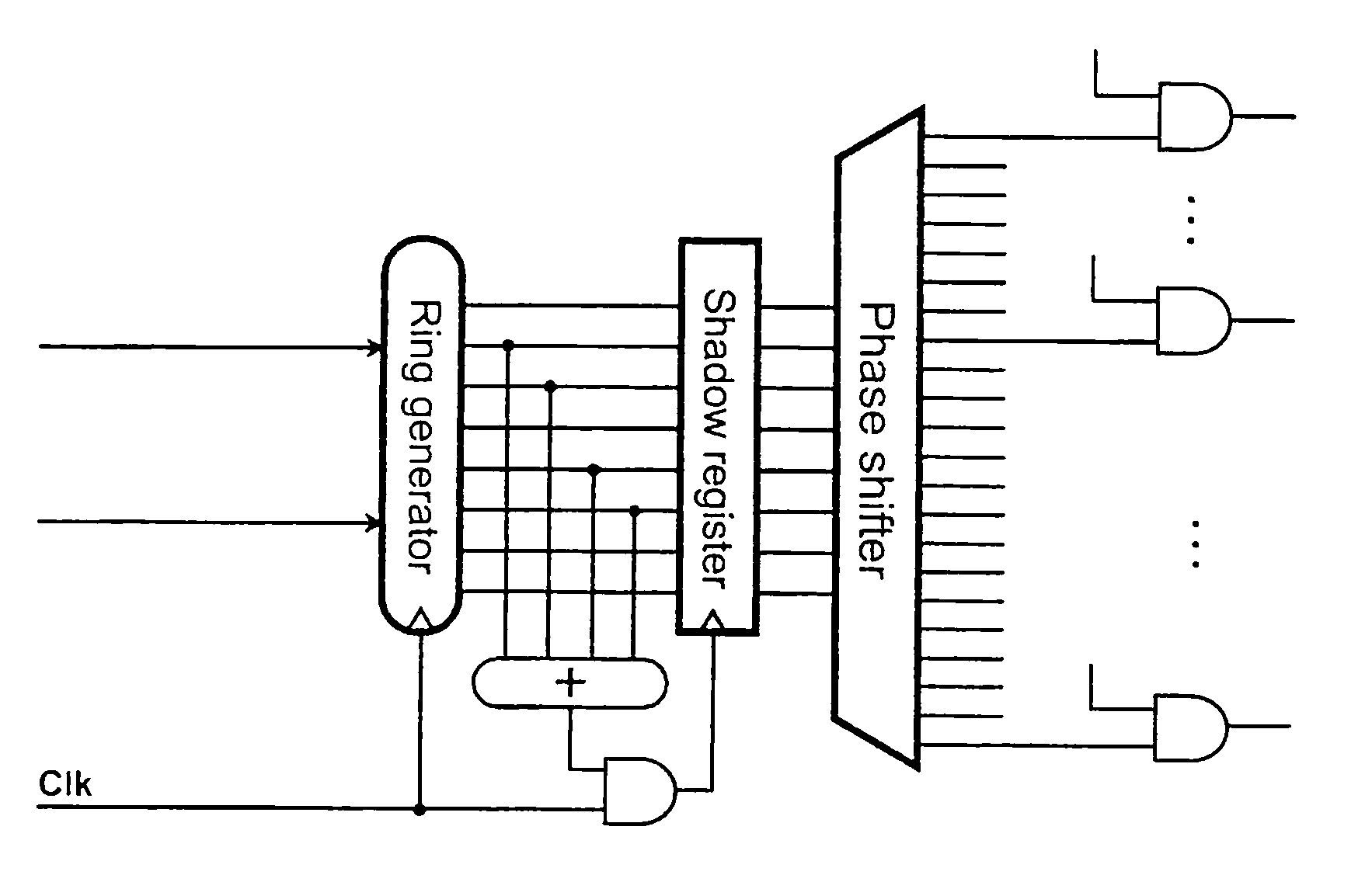
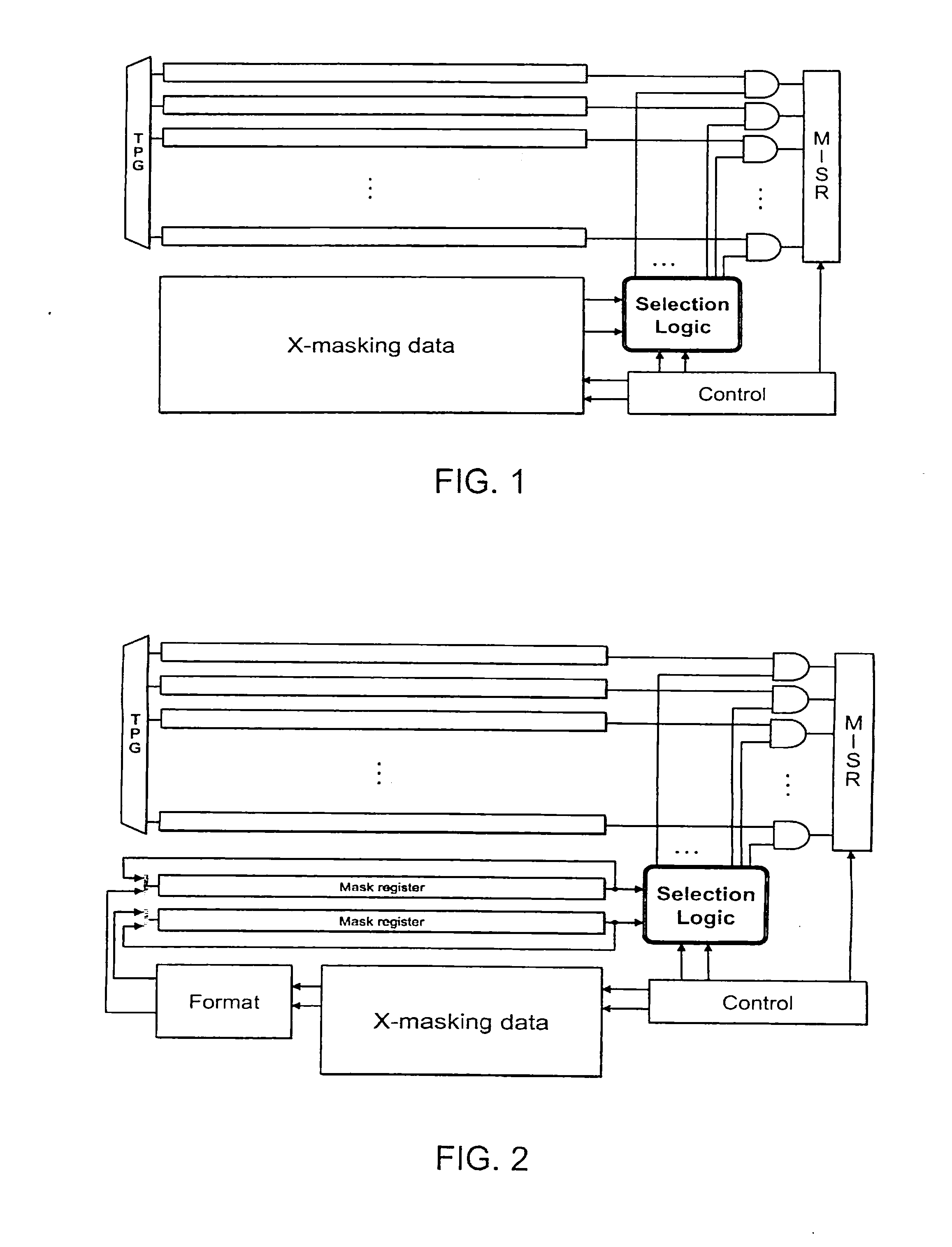
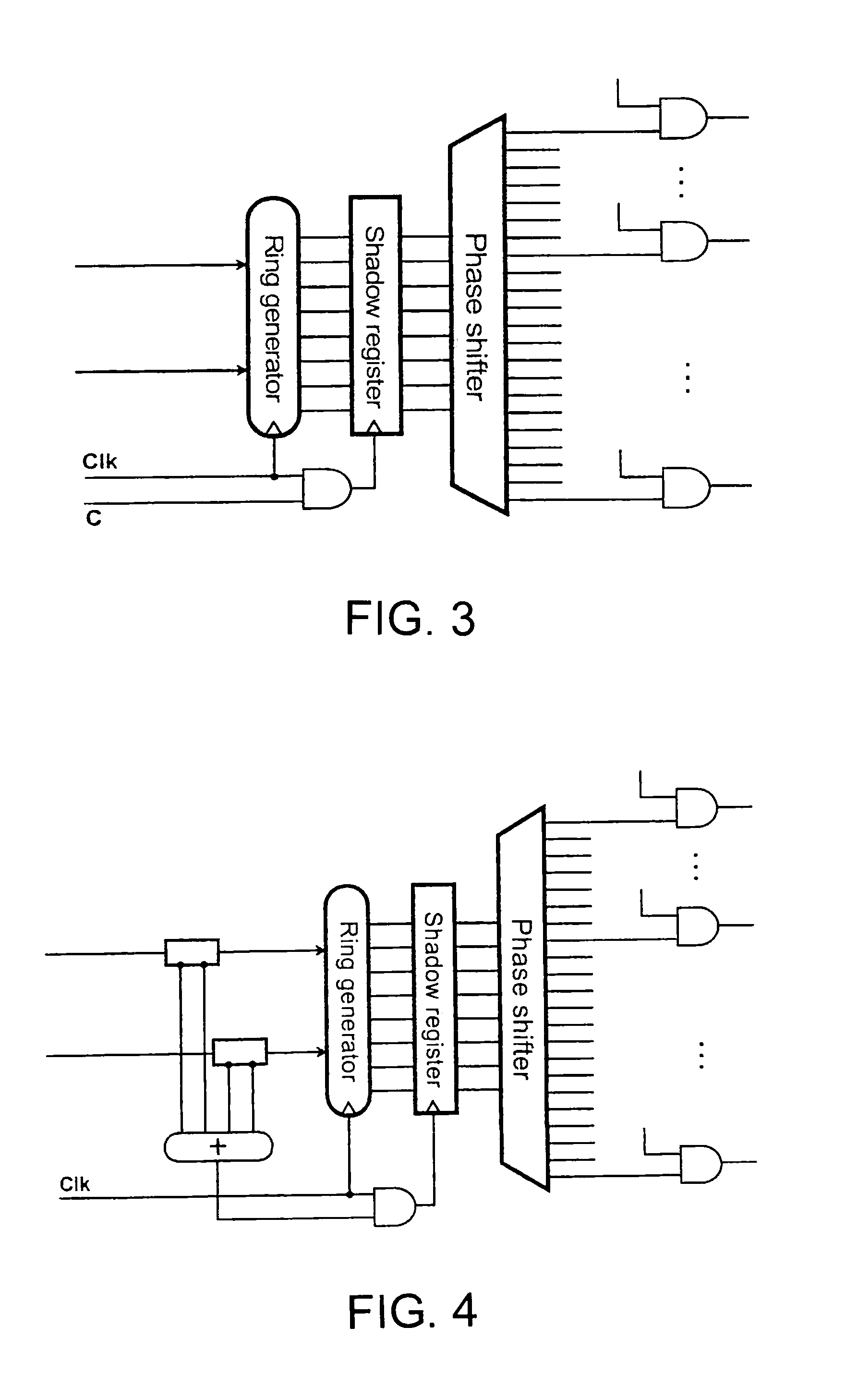
[0004]Aspects of the invention relate to built-in self-test techniques for integrated circuit that address the issue of unknown states. For example, some of the disclosed embodiments use a specialized scan chain selector coupled to a time compactor. The presence of the specialized scan chain selector increases the efficiency in masking X states. Several experimental results confirm that embodiments of the disclosed X-masking scheme do not compromise test quality, but preserve all capabilities of conventional scan-based test and require a small amount of information to control the compactor.
[0005]Furthermore, in some of the disclosed embodiments, the scan chain selection scheme has the ability to perform selective masking of scan chains and to handle a wide range of unknown state profiles (for example, the selective masking can be performed such that all such states can be eliminated in a per-cycle mode while preserving high observability of scan cells that capture errors). Also among the disclosed embodiments are: (1) an architecture of a selector that works with multiple scan chains and time compactors, (2) a method for determining and encoding per cycle scan chain selection masks used subsequently to suppress X states, and (3) a method to handle an over-masking phenomenon.

Problems solved by technology

Several experimental results confirm that embodiments of the disclosed X-masking scheme do not compromise test quality, but preserve all capabilities of conventional scan-based test and require a small amount of information to control the compactor.

Method used


Image

  • Selective Per-Cycle Masking Of Scan Chains For System Level Test
  • Selective Per-Cycle Masking Of Scan Chains For System Level Test
  • Selective Per-Cycle Masking Of Scan Chains For System Level Test

Examples


Embodiment Construction

Overview

[0009]Disclosed below are methods, apparatus, and systems that should not be construed as limiting in any way. Instead, the present disclosure is directed toward all novel and nonobvious features and aspects of the various disclosed methods, apparatus, systems, and equivalents thereof, alone and in various combinations and subcombinations with one another. The present disclosure is not limited to any specific aspect or feature, or combination thereof, nor do the disclosed methods, apparatus, and systems require that any one or more specific advantages be present or problems be solved.

[0010]Although the operations of some of the disclosed methods, apparatus, and systems are described in a particular, sequential order for convenient presentation, it should be understood that this manner of description encompasses rearrangement, unless a particular ordering is required by specific language set forth below. For example, operations described sequentially may in some cases be rear...


PUM


Abstract

Built-in self-test techniques for integrated circuits that address the issue of unknown states. Some implementations use a specialized scan chain selector coupled to a time compactor. The presence of the specialized scan chain selector increases the efficiency in masking X states. Also disclosed are: (1) an architecture of a selector that works with multiple scan chains and time compactors, (2) a method for determining and encoding per cycle scan chain selection masks used subsequently to suppress X states, and (3) a method to handle an over-masking phenomenon.

Description

RELATED APPLICATIONS[0001]This application claims priority under 35 U.S.C. §119 to U.S. Provisional Patent Application No. 61 / 015,663, entitled “Selective Per-Cycle Masking Of Scan Chains For System Level Test,” filed on Dec. 20, 2007, and naming Janusz Rajski et al. as inventors, which application is incorporated entirely herein by reference.FIELD OF THE INVENTION[0002]The present invention is directed to the masking of unknown states during the built-in self-test of integrated circuits. Various embodiments of the invention may be particularly useful for the masking unknown states for built-in self-test techniques using compaction.BACKGROUND OF THE INVENTION[0003]Time compactors of test responses have always had problems dealing with unknown states. Even state of the art compactors do not tolerate unknown states (“X”s or “x-states”) to a high enough standard for today's needs. For example, in BIST applications, a pattern with thousands of scan cells may contain hundreds of scan cel...

Claims


Application Information

Patent Timeline
Patent Type & Authority Applications(United States)
IPC IPC(8): G01R31/3177G06F11/25
CPCG01R31/318547G01R31/3177G06F11/27G01R31/31703G01R31/31723G01R31/31724
Inventor RAJSKI, JANUSZCZYSZ, DARJUSZMRUGALSKI, GRZEGORZMUKHERJEE, NILANJANTYSZER, JERZY
Owner SIEMENS PROD LIFECYCLE MANAGEMENT SOFTWARE INC
Why Eureka
Try Eureka