Hip implant with porous body

a technology of hip implants and porous bodies, applied in the field of hip implants, can solve the problems of limited bone growth into the implant, thin coating on the porous surface, and unsatisfactory surface acceptance, so as to reduce the overall weight of the hip implant, reduce the likelihood of loosening of the implant, and increase the long-term acceptance of the implant in the bone

Inactive Publication Date: 2016-02-23
FOUR MILE BAY
View PDF8 Cites 0 Cited by
  • Summary
  • Abstract
  • Description
  • Claims
  • Application Information

AI Technical Summary

Benefits of technology

[0013]In one exemplary embodiment, the geometric structure of the porous body may be shaped and sized to emulate the shape and size of natural bone surrounding the implant. Specifically, the porous structure of the bone fixation body thus replicates the porous structure of natural bone itself. The porous structure, thus, readily accepts and encourages surrounding bone to grow into and even through the body of the implant.
[0015]As noted, the porous structure of the implant enables bone to grow deeply into or completely through the implant itself. Growth deep into the body of the implant provides an extremely strong interface between the implant and surrounding natural bone. As such, the likelihood that the implant will loosen is greatly reduced. Further, the overall long-term acceptance of the implant in the bone is increased. Further yet, the porous structure of the bone fixation body reduces the overall weight of the hip implant.

Problems solved by technology

These surfaces though are far from ideal in terms of accepting and encouraging bone growth into the body of the implant.
As one disadvantage, porous surfaces are often thin coatings applied to the metallic substrate of the implant.
The depth of bone growth into the implant is limited to the depth of the porous coating.
Bone simply cannot grow completely through the implant or deeply into the body of the implant.

Method used


Image

  • Hip implant with porous body
  • Hip implant with porous body
  • Hip implant with porous body

Examples


Embodiment Construction

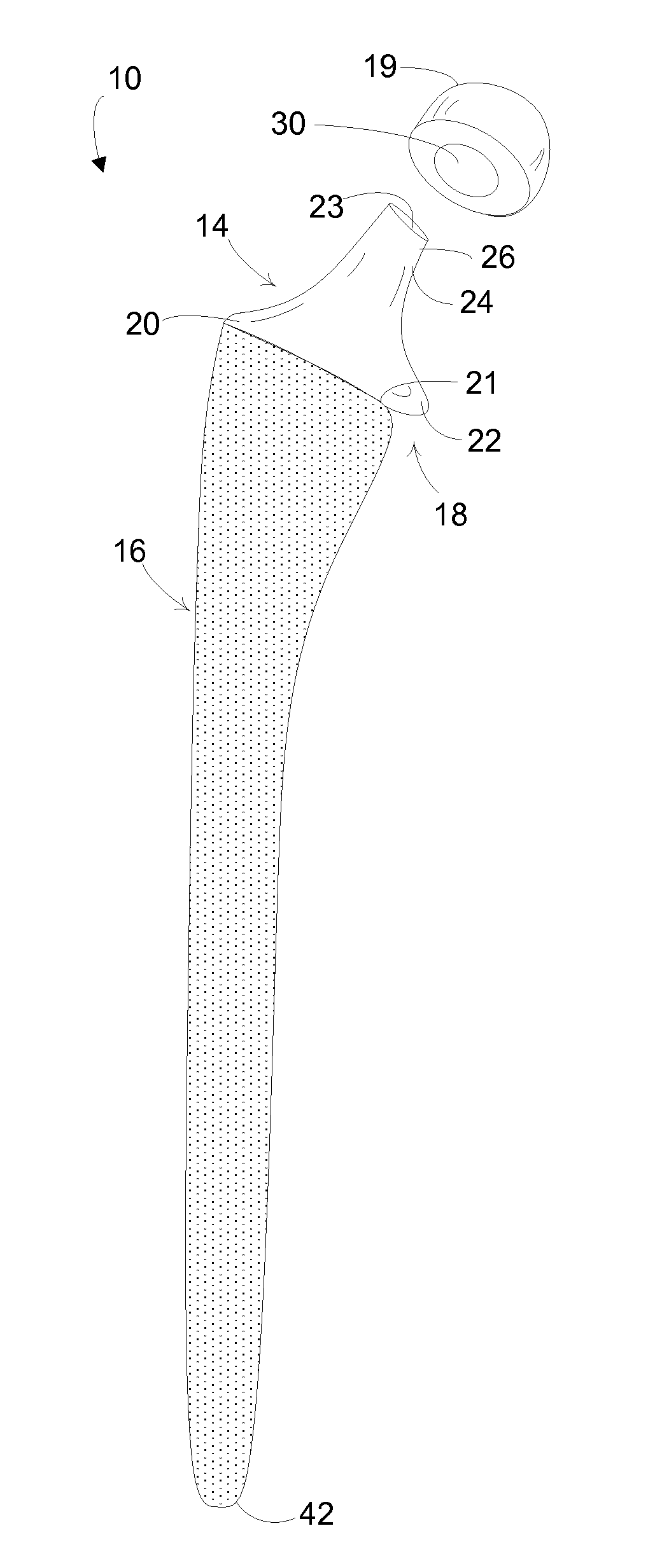
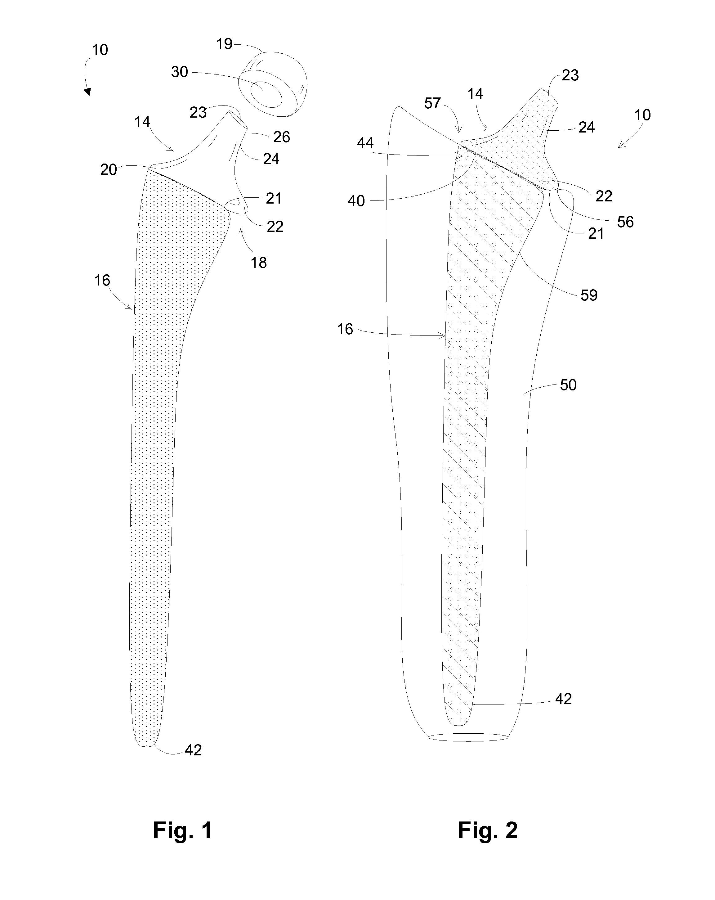
[0025]Referring to FIGS. 1 and 2, a hip implant 10 is shown according to an exemplary embodiment of the invention. Implant 10 is preferably constructed of a biocompatible material such as titanium, titanium alloy, or other metals or alloys suitable for a hip prosthesis. Implant 10 comprises two primary components or bodies, a neck body 14 and a bone fixation body 16.

[0026]The neck body 14 is located at the proximal end 18 of the hip implant 10 and functions to connect the hip implant 10 to a spherically shaped femoral ball 19 and acetabular component (not shown). The neck body extends from a flat or planar distal end surface 21 to a proximal end surface 23. Further, the neck body has a base portion 20 that includes a collar 22 adapted to seat against a resected or end portion of a femur. An interface is adapted to connect the neck body to the femoral ball. A neck portion 24 extends outwardly from the base portion 20. This neck portion has a short cylindrical configuration and has an...


PUM

PropertyMeasurementUnit
porosityaaaaaaaaaa
pore diameteraaaaaaaaaa
diameteraaaaaaaaaa

Abstract

A hip implant having two distinct bodies, a neck body and a bone fixation body. The neck body is formed from a solid metal and has an interface for connecting to a femoral ball. The bone fixation body has an elongated shape and is formed as a porous structure that is inserted into an intramedullary canal of a patient.

Description

CROSS-REFERENCE TO RELATED APPLICATIONS[0001]This application claims priority to and is a continuing application of U.S. patent application having Ser. No. 11 / 409,611 filed on 24 Apr. 2006 which is a continuing application of U.S. patent application having Ser. No. 10 / 446,069 filed on 27 May 2003, which are incorporated herein by reference.FIELD OF THE INVENTION[0002]The disclosure herein generally relates to hip implants for osseointegration into bone and, more particularly, to hip implants having a porous body.BACKGROUND OF THE INVENTION[0003]Much effort has been directed to integrating hip implants into surrounding bone. Ideally, a hip implant would be placed into the femur, and thereafter bone would readily grow into the surface of the implant. To achieve this objective, many different surface technologies have been applied to hip implants. In some instances, the surface of the implant is roughened, grit-blasted, plasma-sprayed, or microtextured. In other instances, the surface ...

Claims


Application Information

Patent Timeline
Patent Type & Authority Patents(United States)
IPC IPC(8): A61F2/36A61F2/30A61F2/00A61F2/28
CPCA61F2/3609A61F2/3601A61F2002/3652A61F2002/30013A61F2/30767A61F2/36A61F2/3662A61F2002/2817A61F2002/30112A61F2002/30125A61F2002/30136A61F2002/30153A61F2002/30154A61F2002/30156A61F2002/30158A61F2002/30332A61F2002/30354A61F2002/30367A61F2002/30403A61F2002/30604A61F2002/30677A61F2002/30838A61F2002/30906A61F2002/3092A61F2002/30925A61F2002/30957A61F2002/30968A61F2002/3611A61F2002/3625A61F2002/3631A61F2002/365A61F2220/0025A61F2220/0033A61F2230/0004A61F2230/0008A61F2230/0019A61F2230/0021A61F2230/0023A61F2230/0026A61F2250/0024A61F2310/00023A61F2310/00796A61F2230/0063A61F2230/0076A61F2002/30011A61F2002/30331B22F7/04A61F2/3607
Inventor LYREN, PHILIP, SCOTT
Owner FOUR MILE BAY
Why Eureka
Try Eureka