Photoswitch

a technology of a switch and a circuit, applied in the field of photo switches, can solve the problems of increasing the complexity of the circuit, increasing the cost of production, and increasing the instability of the circuit, and achieve the effect of more complicated and expensiv

Active Publication Date: 2014-12-16
QICHENG ELECTRICAL EQUIP
View PDF18 Cites 9 Cited by
  • Summary
  • Abstract
  • Description
  • Claims
  • Application Information

AI Technical Summary

Benefits of technology

[0005]In view of the above-described problems, one of the objectives of this invention is to provide a photoswitch with a simplified circuit, in order to solve problems of photoswitches of prior art utilizing two individual controlling circuits for turning on and turning off the lamp that is more complicated and expensive.
[0022]① It is advantageous for the photoswitch of this invention, to comprise a DC power supply, a luminance controlling circuit in electrical connection with the DC power supply, and a lightening apparatus controlled by the luminance controlling circuit; the luminance controlling circuit comprises a relay RL1, a trigger circuit module adapted for switching on or switching off the relay RL1, a delay discharge circuit module adapted for supplying power for the trigger circuit module and activating the trigger circuit module, a photosensitive element in series connection with the delay discharge circuit module, and an adjusting circuit module adapted for setting a value of luminance for turning on or turning off a light; as the photoswitch of this invention only comprises one set of controlling circuit adapted for setting the luminance values of turning on and turning off the light, which has been considerable simplified comparing with the photoswitch of prior art having two sets of controlling circuits, in addition, the photoswitch of this invention comprises less numbers of electronic elements, so as to save cost and achieve higher electrical stability.
[0023]② It is advantageous for the photoswitch of this invention, to further comprise a delay discharge circuit module. When the lightening luminance changes, the changing of the voltage of the base of the triode Q1 may be delayed due to the discharge of the capacitor C1, which may avoid interference caused by short lightening from lamps of automobiles or other light sources, so that the lightening apparatus may not be turned off due to instantaneous lightening as well as being turned on due to the darkening of the instantaneous light. It is guaranteed that the photoswitch of this invention will be working at a stable state and the life of the lightening apparatus may be extended.
[0024]{circle around (3)} It is advantageous for the photoswitch of this invention, to further comprise a relay to control the turning on and off the lightening apparatus, and the controlling circuit module and the lightening circuit module are separated from each other, which remains the constancy of the current through the lightening circuit, so as to control a LED lamp, an energy saving lamp, an incandescent lamp and so on so as to expanding the using range of the photoswitch.
[0025]④ It is advantageous for the photoswitch of this invention, to further comprise a triode Q1 the emitter of which is in connection with the negative of the DC power supply through the resistor R3 that is adapted for limiting current, reducing current of the emitter of the triode Q1 so as to protect the electronic elements.

Problems solved by technology

Although the abovementioned device may set different luminance values for turning on and off a lamp, utilizing two photoresistors to form two control circuits for the luminance control may result in use of too many electronic elements, increase complexity of circuit, and raise the cost of production.
Furthermore, too many electronic elements used may cause instability of the circuit.

Method used


Image

  • Photoswitch
  • Photoswitch
  • Photoswitch

Examples


embodiment 1

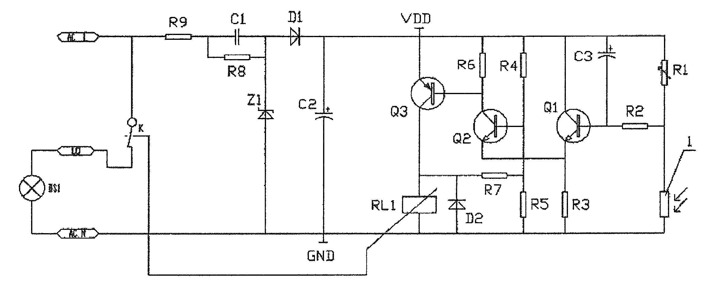
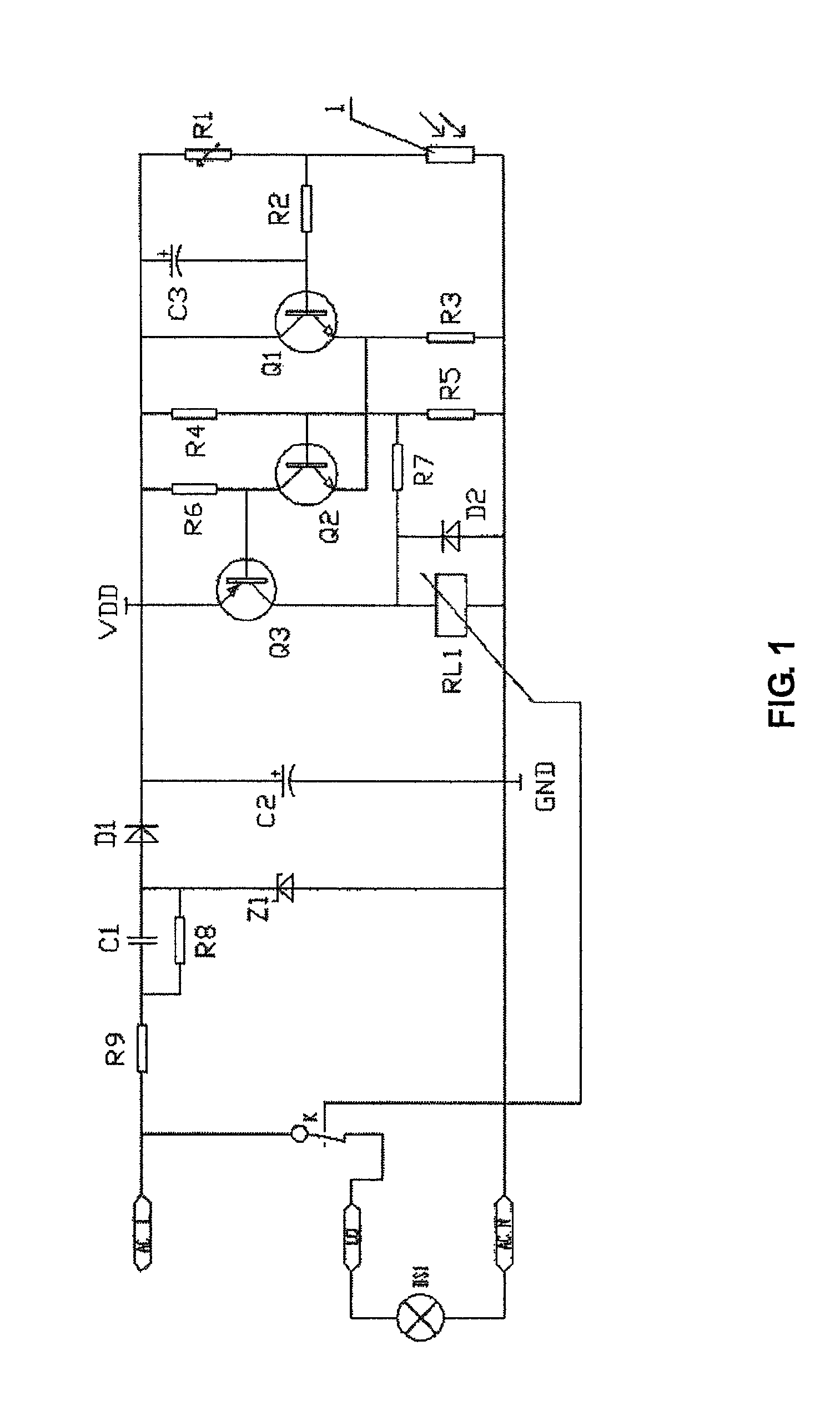
[0030]Referring to FIG. 1, a preferred embodiment of this invention is showed. The photoswitch of this embodiment comprises a DC power supply, a luminance controlling circuit in electrical connection with the DC power supply, and a lightening apparatus controlled by the luminance controlling circuit; the luminance controlling circuit comprises a relay RL1, a trigger circuit module adapted for switching on or switching off the relay RL1, a delay discharge circuit module adapted for supplying power for the trigger circuit module and activating the trigger circuit module, a photosensitive element in series connection with the delay discharge circuit module, and an adjusting circuit module adapted for setting a value of luminance for turning on or turning off a light.

[0031]In this embodiment, the DC power supply supplies 24V obtained from an 110V AC power supply through a limited current circuit for limiting current and reducing voltage and a rectification circuit for rectifying and fil...

embodiment 2

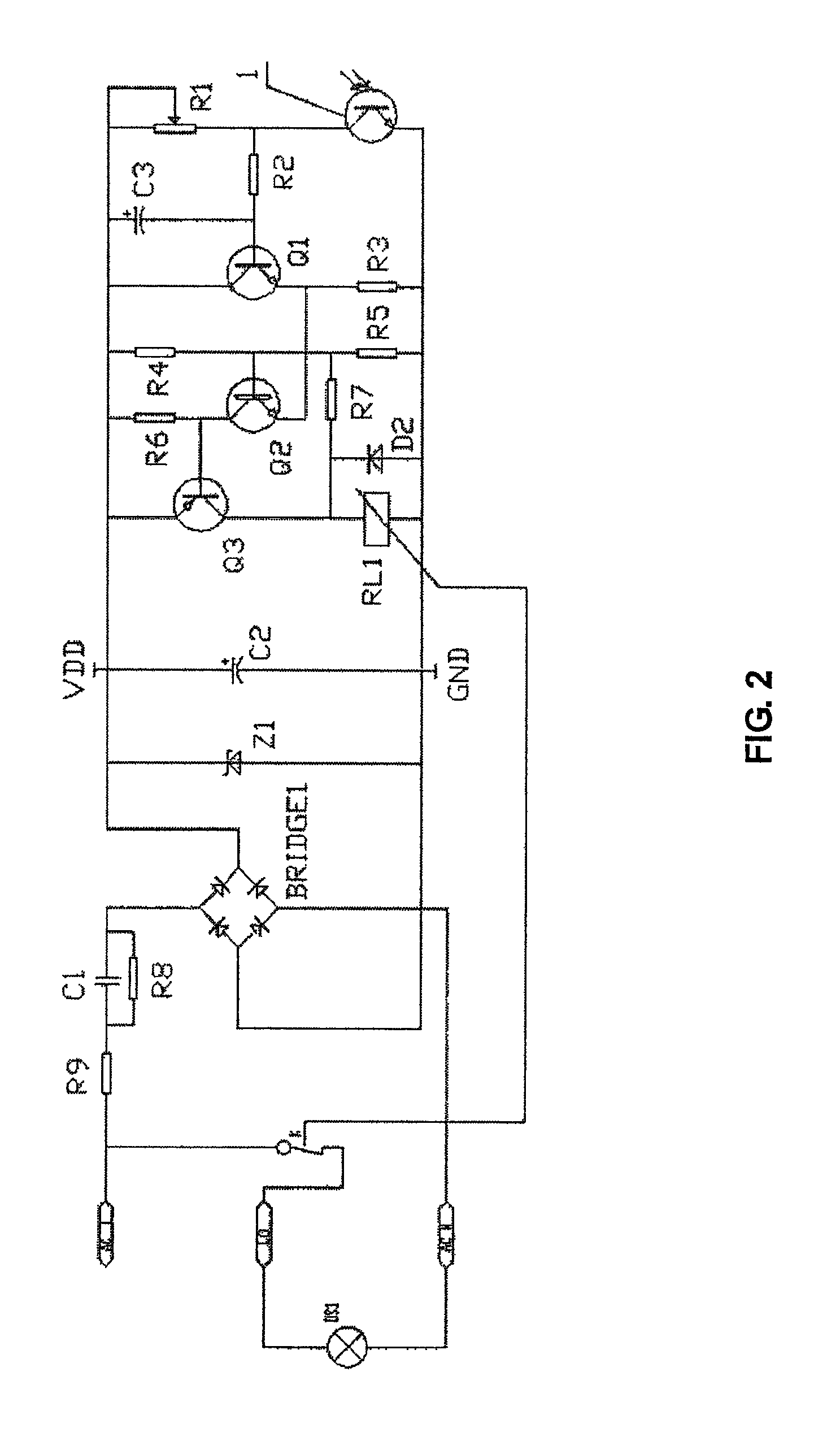
[0046]Referring FIG. 2, the components of this embodiment are basically the same as the embodiment 1, except:[0047](1) replacing the photoresistor with a phototriode, the collector of which is in connection with the current output end of the resistor R1 and the emitter is in connection with the negative electrode of the DC power supply.[0048](2) replacing the diode D1 with a rectifier bridge BRIGE1.[0049](3) The lightening apparatus is LED lamp.

[0050]The steps for setting luminance for turning on and turning off the lamp are the same as the steps mentioned in example 1.

[0051]In the other embodiment, the lightening apparatus may be an incandescent lamp. The photosensitive element 1 may be a photodiode.

[0052]In the other embodiment, the contact of relay RL1 may be normally open contact, and the current value of the subcircuit with the resistor R7 and the relay RL1 is smaller than a release current value of the relay RL1.

[0053]In the other embodiment, the power for the photoswitch may ...


PUM


Abstract

A photoswitch includes a DC power supply, a luminance controlling circuit and a lightening apparatus. The luminance controlling circuit includes a relay RL1, a trigger circuit module, a delay discharge circuit module, a photosensitive element and an adjusting circuit module. The trigger circuit module includes a NPN triode Q1, a NPN triode Q2, NPN triode Q3, a resistor R3 and a resistor R6; the adjusting circuit module includes a resistor R4 and a resistor R5 and a resistor R7, one end of which is in connection with the current output end of the resistor R4 and the other of is in connection with the current input end of the relay RL1; a current value of a subcircuit with the resistor R7 and the relay RL1 is smaller than a pull-in current value or a release current value of the relay RL1.

Description

CROSS REFERENCE TO RELATED APPLICATIONS[0001]This is a national stage application of PCT / CN2012 / 079426, filed on Jul. 31, 2012, which claims priority to Chinese Patent Application No. 201210207199.6, filed on Jun. 21, 2012. This application claims the benefits and priority of these prior filed applications and incorporates the disclosures of these prior filed applications by reference in their entirety.FIELD OF THE INVENTION[0002]The present invention relates to a device for switching a circuit, in particularly relates to a photoswitch.DESCRIPTION OF THE RELATED ART[0003]A photoswitch is a device for switching a lamp automatically in terms of illumination intensity of light, which may not only be labor saving, but also energy saving. Hence, it is widely used in our daily life. In order to achieve the purpose of saving energy, generally, the values of luminance intensity for turning on and off the lamp are different from each other, and may be set according to the conditions of the s...

Claims


Application Information

Patent Timeline
Patent Type & Authority Patents(United States)
IPC IPC(8): H05B37/02
CPCH05B37/0218Y02B20/46H05B47/11Y02B20/40
Inventor YE, XUANFENG
Owner QICHENG ELECTRICAL EQUIP
Why Eureka
Try Eureka