
Stretch valve balloon catheter and methods for producing and using same

a technology of stretch valve and balloon catheter, which is applied in the field of catheters, can solve the problems of increasing the burden on the already stressed health care system, increasing the cost and burden of health care, and not having a catheter constructed, and achieves the effect of quick and rapid deflating

Active Publication Date: 2015-12-24
MAYSER
View PDF0 Cites 0 Cited by
  • Summary
  • Abstract
  • Description
  • Claims
  • Application Information

AI Technical Summary

Benefits of technology

[0041]The low-pressure balloon catheter of the present invention prevents injury by having the balloon automatically deflate before an injury can occur, for example, when being forced to withdraw from the bladder or being forced to inflate within a urethra. The stretch valve balloon catheter of the present invention prevents injury by having the balloon automatically deflate before an injury can occur, for example, when being forced to withdraw from the bladder prior to physician-scheduled manual deflation. While the catheters of the present invention makes it a safer device for urinary drainage, the present invention can also be used for any procedures in which balloons are used to occlude cavities. Examples of these procedures include coronary artery vessels and peripheral vascular vessels, such as the aorta and extremity vessels. Balloon dilations of other lumens, such as ureters and the esophagus, are also candidates for use of the catheter of the present invention. Further, the mechanism of pressure release can be used for any fluid or air-filled device such as tissue expanders, percutaneous devices, and the like.
[0042]Some of the embodiments of the present invention utilize a valve (e.g., a slit valve or a stretch valve) that permits reuse when utilized. With embodiments having no such valves, the invention is a single use catheter after deflation occurs. Although deflation of such a single-use catheter renders it useless, the act of immediate deflation protects the patient from serious harm and the cost of replacing a catheter is minimal as compared to the significant cost of treating catheter-induced injury. Prevention of such injuries is becoming more and more important because the injuries are commonplace. The increase occurs for a number of reasons. First, a greater percentage of the population is aging. Second, there is a current trend to use less-skilled health care personnel to perform more procedures and to be responsible for treatment, both of which save the hospitals and doctors money. The shortage of nursing professionals (e.g., R.N.s) exacerbates this trend. The present tendency is to use nursing professionals for more functions, such as administration and delivery of medications. This leaves only the least-skilled technicians with the task of taking vital signs and inserting catheters. Under such circumstances, more injuries are likely and do, in fact, occur. Lastly, catheter-related complications are becoming more severe due to the increased use of anticoagulation medication, such as PLAVIX®, that is frequently prescribed in treating cardiovascular disease.
[0045]The added benefit of the present invention is not just for safety, significant financial benefits arise as well. It is believed that catheter-induced injuries are much more common than public documentation suggests. Catheter-related trauma occurs no less that once a week in a large metropolitan hospital. Usually, each incident not only increases the patient's hospital stay substantially, but also the expense of the stay. Each incident (which is usually not reimbursed by insurance) can increase the cost to the hospital by thousands of dollars, even tens or hundreds of thousands of dollars. This is especially true when the patient brings a personal injury action against the hospital, physician(s), and / or staff. And, when additional surgery is required to repair the catheter-induced injury, increased expense to the hospital is not only substantial, if litigation occurs as a result of the injury, damages awarded to the patient can run into the millions of dollars. The catheters and methods of the present invention, therefore, provide a safer catheter that has the possibility of saving the medical industry billions of dollars.
[0046]To prevent urethra tearing occurrences due to premature-improper inflation of the balloon and / or due to premature removal of an inflated balloon, an exemplary embodiment of the invention of the instant application provides various balloon safety valves. Such valves are configured to release the inflation liquid from the balloon before injury occurs.
[0050]Another exemplary embodiment of the present invention provides the catheter with a balloon that inflates with virtually no pressure. As used herein, “virtually no pressure,”“zero-pressure” and “low-pressure” are used interchangeably and are defined as a range of pressure between approximately standard atmospheric pressure and 0.3 atmospheres (5 psig). This is in contrast to “high-pressure,” which is greater than approximately 1.5 atmospheres (22 psig). With such a configuration, the zero-pressure balloon can be deflated with virtually no force. As such, when the clinician attempts to inflate the zero-pressure balloon of the present invention within a urethra, the balloon simply does not inflate. Likewise, when the already inflated balloon within the bladder is forced into the urethra, such deflation needs virtually no pressure to collapse the balloon to fit into the urethra. In both circumstances, injury to the urethra is entirely prevented.
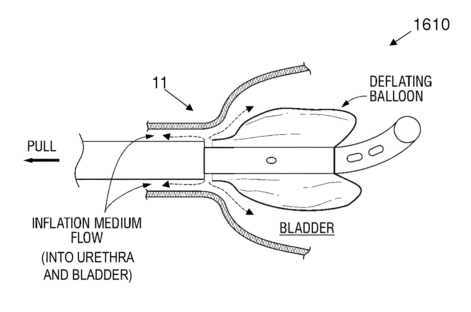
[0051]Further exemplary embodiments of the present invention that prevents urethra tearing occurrences due to premature removal of an inflated balloon provides a balloon catheter with a stretch valve and methods for manufacturing and using such a valved catheter. In these variations, the invention takes advantage of the fact that premature removal of the inflated balloon catheter requires stretching of the catheter at the proximal side of the balloon. The valved catheter can be configured with a release mechanism that is a function of elongation. With short elongations, the balloon remains inflated however, when pulled beyond a preset limit, the valve automatically opens and drains the fluid filling the balloon. Some variations allow the balloon to even be refilled if deflation occurs without any injury. In either case, injury is prevented. Description of one exemplary embodiment herein in a way that separate from other exemplary embodiments is not to be construed mean that the one embodiment mutually exclusive of the other exemplary embodiments. The various exemplary embodiments of the safety catheter mentioned herein can be used separately and individually or they can be used together in any combination.

Problems solved by technology

Prior art catheters are not constructed to prevent tearing of the urethra during a catheter implanting procedure and are not constructed to break in any predefined way.
These complications are responsible for increases in hospital stays, excessive bleeding, mortality, as well as morbidity.
They also cause an increased expense and burden on the already-stressed health care system.
First, and probably most common, is improper placement of the catheter.
Because of the unique anatomy of the male urethra, placing a urethral catheter for urinary drainage can be difficult.
A problem arises when the physician, technician, or nurse thinks that the catheter is actually in a proper position when it is not.
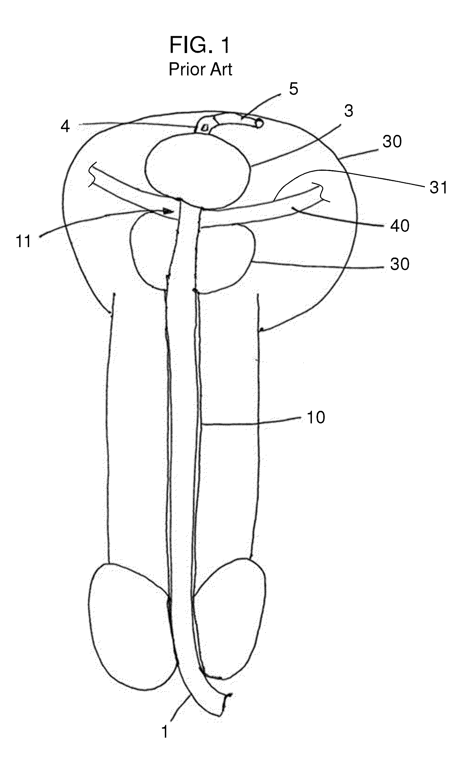
Therefore, if the balloon catheter is not inserted far enough, inflation of the balloon 3 will cause serious injury to the urethra 10.
Both of these improper insertions cause severe bleeding and damage.
Tearing of the urethra 10 in this way causes bleeding and allows bacteria to enter into the bloodstream at the tear site, thus causing the subsequent bladder infection.
Significant bleeding can become life threatening.
Also, without sufficient and immediate venting of the balloon inflation fluid after improper placement, an accidental or intentional pull on the catheter externally can and does cause extensive bodily harm to the patient.
Life threatening bleeds, especially in patients who are anticoagulated, can and do occur.
Also when the urine is infected, as in immunocompromised patients and the elderly, the bacteria enter the blood stream and can cause serious infections (e.g., sepsis), which frequently can lead to death.
If the patient survives the initial trauma, then long-term complications, such as strictures, can and usually do occur.
Strictures cause narrowings within the urine channel and usually require additional procedures and surgeries to correct.
The tubing may inadvertently become fixed while the patient is still moving, at which time a sudden jerk is imparted upon the balloon and pulls the balloon into the urethra, which tears the urethra, causing severe pain and bleeding.
Hundreds of thousands of such iatrogenic injuries occur each year—all of which need to be prevented, not only for patient safety, but also because the cost imposed on the medical health industry for each injury is enormous.
Yet another scenario occurs when the patient deliberately pulls on the catheter, thereby causing self-induced pain and injury to the urethra.
During the spasm, the confused patient often tugs and pulls on a catheter, which results in injury.
Under such circumstances, insurance typically does not cover the resulting extensive medical expenses.

Method used


Image

  • Stretch valve balloon catheter and methods for producing and using same
  • Stretch valve balloon catheter and methods for producing and using same
  • Stretch valve balloon catheter and methods for producing and using same

Examples


first embodiment

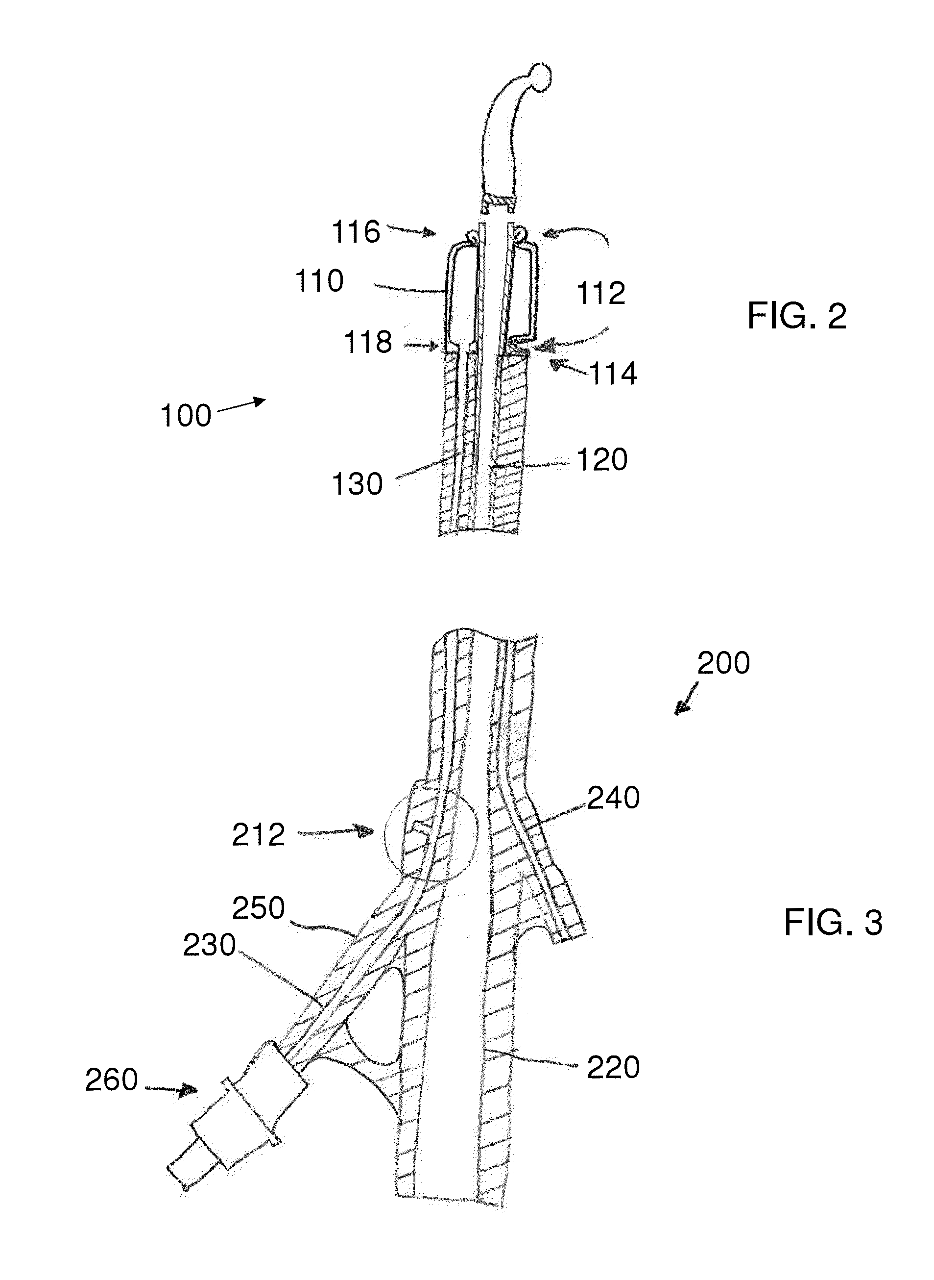
[0106]Referring now to the figures of the drawings in detail and first, particularly to FIG. 2 thereof, there is shown a pressure-limiting balloon catheter 100 that does not inflate past the tearing limit of a lumen in which the catheter 100 is placed, for example, in the urethra.

[0107]To prevent occurrences of urethra tearing due to premature-improper inflation of the balloon and / or due to premature removal of an inflated balloon, the invention of the instant application provides the balloon 110 with a balloon safety valve 112. As set forth above, in a balloon 3 of a conventional catheter (see reference numerals 1 to 5 in FIG. 1), the high-pressure balloon 3 is fixed to the outer surface of the fluid drainage lumen 120 (not shown in FIG. 1) and is not intended to be removed therefrom or to burst thereon unless an extraordinary amount of inflation occurs. Such a tearing event is not supposed to occur under any circumstances during use with a patient. If such an event happens, the ma...

second embodiment

[0113]the one-use breaking safety valve of a pressure-limiting balloon catheter 200 is shown in FIG. 3. The catheter 200 has a fluid drainage lumen 220, a balloon inflation lumen 230, and a secondary lumen 240.

[0114]The fluid drainage lumen 220 is connected fluidically to the body cavity (i.e., the bladder 30) for draining fluid from the body cavity.

[0115]The secondary lumen 240 can be used for any purpose, for example, for housing the radiation line that will supply energy to the radiation coil 2. It can also be used for injecting fluid into any distal part of the catheter 200 or even the body cavity itself.

[0116]The balloon inflation lumen 230 begins at a proximal end with an inflating connector 260 that, in an exemplary embodiment, is one part of a luer connector. The balloon inflation lumen 230 continues through the body of the catheter 200 all the way to the balloon 110 and is fluidically connected to the interior of the balloon 110.

[0117]Alternatively or additionally, the ball...


PUM


Abstract

A safety catheter includes a flexible, multi-lumen shaft having an outer diameter, a distal tip, a proximal catheter end with a drain end and a proximal inflation end. The multi-lumen shaft defines a drain lumen, a distal hollow balloon portion, at least one inflation lumen, and a drainage port. A hollow stretch valve is coaxially disposed in the drainage lumen and has a radially self-expandable proximal section fixedly connected within the drain lumen by self-expansion, a flexible intermediate section longitudinally movable within the drain lumen, and a distal plug movably positioned in the drain lumen to prevent fluid from passing through the drainage port in a steady state and being slidably disposed within the drain lumen such that, in a stretched state when the proximal catheter end is stretched, the distal plug slides within the drain lumen to permit the inflation fluid to pass through the drainage port.

Description

CROSS-REFERENCE TO RELATED APPLICATIONS[0001]This application:[0002]claims the priority, under 35 U.S.C. §119, of copending U.S. Provisional Patent Application No. 61 / 637,690, filed Apr. 24, 2012;[0003]is a continuation-in-part of U.S. patent application Ser. No. 11 / 339,258, filed Jan. 25, 2006, now U.S. Pat. No. 7,883,503 (which application claims the benefit under 35 U.S.C. §119(e) of U.S. Provisional Patent Application Nos. 60 / 647,204 and 60 / 647,205, both filed Jan. 26, 2005);[0004]is a continuation-in-part of U.S. patent application Ser. No. 12 / 943,453, filed Nov. 10, 2010 (which application claims the benefit under 35 U.S.C. §119(e) of U.S. provisional application No. 61 / 260,271 filed Nov. 11, 2009);[0005]is a continuation-in-part of U.S. patent application Ser. No. 13 / 707,952, filed Dec. 7, 2012 (which application claims the benefit under 35 U.S.C. §119(e) of U.S. provisional application No. 61 / 637,690, filed Apr. 24, 2012); and[0006]is a continuation-in-part of U.S. patent ap...

Claims


Application Information

Patent Timeline
Patent Type & Authority Applications(United States)
IPC IPC(8): A61M25/00
CPCA61M25/0017A61B5/205A61M25/04A61M25/10185A61M2025/1093A61M2210/1085A61M25/10181A61M25/10184
Inventor PINCHUK, LEONARDKALSER, GARY A.MAYBACK, GREGORY L.LEONE, JAMES
Owner MAYSER
Learn More