Connector and connector assembly

a technology of connectors and assemblies, applied in the direction of incorrect coupling prevention, coupling device connections, electrical devices, etc., can solve the problems of reducing the resilient force of the lock arm and the inability to reliably strengthen the lock arm, so as to reduce the height of the connector

Active Publication Date: 2014-12-30
SUMITOMO WIRING SYST LTD
View PDF32 Cites 39 Cited by
  • Summary
  • Abstract
  • Description
  • Claims
  • Application Information

AI Technical Summary

Benefits of technology

[0009]Part of the detector is accommodated in the accommodating recess of the lock arm when the detector reaches the detection position. Thus, the lock arm and the detector overlap in the deforming direction (i.e. the height direction) and the corresponding height dimension of the connector can be reduced. The accommodating recess is open toward the deformation space for the lock arm and toward the back, but is not open on a front part connected to the housing main body. Thus, a reduction the lock arm is strong and locking reliability is good.
[0021]The moderately inclined surface may be formed by making the angle of inclination smaller to make the entire area of the front surface of the protrusion and that of the front surface of the auxiliary protrusion flat. However, if the moderately inclined surface is formed in this way, it means a reduction in the height of the upper end of the auxiliary protrusion. Thus, an overlap margin between the auxiliary protrusion and the lock projection in the height direction or the deforming direction is reduced and the height of the connector cannot be sufficiently reduced. However, in the present invention, the moderately inclined surface preferably is formed only in the area of the front surface of the protrusion not corresponding to the auxiliary protrusion in the width direction. Thus, even if the moderately inclined surface is formed, the height of the upper end of the auxiliary protrusion is unchanged and the overlap margin between the auxiliary protrusion and the lock projection in the height direction is not reduced. Therefore, there is no problem in reducing the height of the connector.

Problems solved by technology

Thus, the through hole reduces a resilient force of the lock arm, and the lock arm is not reliably strong.

Method used


Image

  • Connector and connector assembly
  • Connector and connector assembly
  • Connector and connector assembly

Examples


first embodiment

[0101]As shown in FIGS. 24 to 27, a substantially rectangular block-shaped protrusion 102 projects up near a front part of a resilient arm 101 of the detector 100. An auxiliary protrusion 103 having substantially the same shape as in the first embodiment projects up on the upper end surface of the protrusion 102. The auxiliary protrusion 103 is in the form of a rib extending in forward and backward directions FBD in a substantially widthwise central part of the upper or outer end surface of the protrusion 102. Thus, the auxiliary protrusion 103 is narrower than the protrusion 102.

[0102]A projecting distance of the auxiliary protrusion 103 along the deforming direction DD (the height direction HD) from the protrusion 102 is smaller than the projecting distance of the protrusion 102 from the resilient arm portion 101 along the deforming direction DD. Further, the upper surface of the auxiliary protrusion 103 is tapered to incline down or in toward the back. The auxiliary protrusion 10...

second embodiment

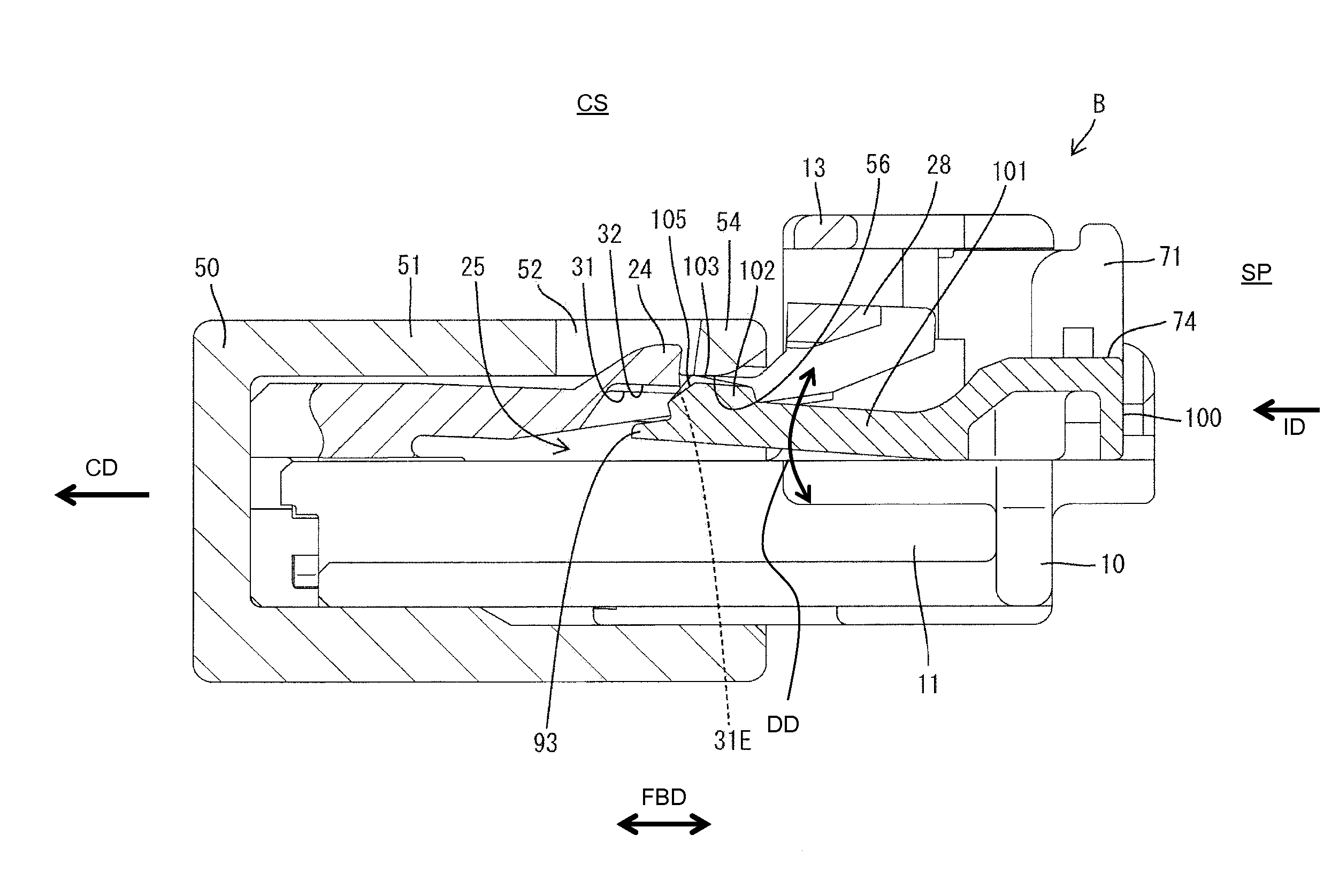
[0109]The narrow auxiliary protrusion 103 of the connector B of this second embodiment projects in the height direction on the protrusion 102 and a part of the inner surface of the accommodating recess 31 is recessed to form the auxiliary recess 32 for receiving the auxiliary protrusion 103 at the detection position DP. The steeply inclined surface 104 is formed at an area of the front surface of the protrusion 102 corresponding to the auxiliary protrusion 103 in the width direction WD and is inclined with respect to forward and backward directions FBD. The steeply inclined surface 104 is substantially continuous and flush with the front surface of the auxiliary protrusion 103. Further, the areas of the front surface of the protrusion 102 not corresponding to the auxiliary protrusion 103 in the width direction WD form the moderately inclined surfaces 105 and have a smaller angle of inclination with respect to forward and backward directions FBD than the steeply inclined surface 104....

third embodiment

[0114]A rear end part of the accommodating recess 35 of the third embodiment is cut obliquely to form at least one escaping portion 36 that is open in or down and back. The escaping portion 36 avoids interference of an auxiliary protrusion 103 with a rear end part of the lower surface of a lock projection 24 as the moderately inclined surfaces 105 slide in contact with an opening edge 31E. Therefore, a guide function by the sliding contact of the opening edge 31E and the moderately inclined surfaces 105 is displayed continuously until the insertion of the auxiliary protrusion 103 into the auxiliary recess 35 (insertion of a protrusion 102 into an accommodating recess 31) is complete.

[0115]The present invention is not limited to the above described and illustrated embodiment. For example, the following embodiments are also included in the technical scope of the present invention.

[0116]The detecting member may be configured to be incapable of restricting the resilient deformation of t...


PUM


Abstract

A lock arm (12) is cantilevered back from a front end part of a housing main body (11). The lock arm (12) includes an accommodating recess (31) that is open toward a deformation space (25) therefor and toward the back. When the housing main body (11) is connected properly to a mating housing (50) and a detector (70) is pushed from a standby position to a detection position, a part of the detector (70) is inserted into the accommodating recess (31).

Description

BACKGROUND OF THE INVENTION[0001]1. Field of the Invention[0002]The invention relates to a connector and to a connector assembly.[0003]2. Description of the Related Art[0004]U.S. Pat. No. 6,712,635 discloses a connector with a mating housing and a housing main body connectable to the mating housing. A lock arm is cantilevered back from a front part of the housing main body and is configured to engage a lock receiving portion of the mating housing to hold the housing main body and the mating housing in a connected state. A detector is mounted on the housing main body and is movable from an initial position to a detection position via a standby position. The detector configured to detect whether the mating housing has been connected properly to the housing main body based on whether the detector can be moved from the standby position to the detection position.[0005]An engaging portion is formed on a rear part of the lock arm and a through hole penetrates through a front part of the lo...

Claims


Application Information

Patent Timeline
Patent Type & Authority Patents(United States)
IPC IPC(8): H01R13/641H01R13/627
CPCH01R13/641H01R13/6272
Inventor KON, AKIHIRONORO, YUTAKA
Owner SUMITOMO WIRING SYST LTD
Why Eureka
Try Eureka