Construction machine

a construction machine and construction technology, applied in mechanical machines/dredgers, soil shifting machines/dredgers, transportation and packaging, etc., can solve the problems of increasing man-hours and parts, and achieve the effect of enhancing stability during traveling and work operation

Active Publication Date: 2015-03-03
NIHON KENKI CO LTD
View PDF28 Cites 9 Cited by
  • Summary
  • Abstract
  • Description
  • Claims
  • Application Information

AI Technical Summary

Benefits of technology

[0009]In view of the above-discussed problems with the prior art, it is an object of the present invention to provide a construction machine which makes it possible to dispose the indoor unit on the footrest section of the floor member with a small number of parts and less man-hour while water is prevented from entering the indoor unit at the time of washing the interior of the operating room with water.
[0014]As a result, since it is unnecessary for an opening for disposing the indoor unit to be provided in the footrest section of the floor member, it is possible to reliably prevent water from entering the indoor unit at the time of washing the interior of the operating room with water, without needing to separately provide a seal member or the like. In consequence, at the time of washing the interior of the operating room with water, the cleaning operation can be performed efficiently since it is unnecessary to give extra consideration to the indoor unit being splashed with water. Furthermore, it is possible to reduce the number of parts such as the seal member, the tray, and the cover as well as man-hour for processing the footrest section.
[0020]With this arrangement, as the box body whose upper side is open is mounted on the unit mounting surface of the footrest section, the upper side of the box body can be closed by making use of the unit mounting surface as the closing surface. Accordingly, since the vertical dimension of the box body can be made small by the amount in which the top surface is omitted, the height dimension of the upper revolving structure can be reduced to a low level, making it possible to enhance stability during traveling and work operation. Meanwhile, the accommodating space on the lower side of the floor member above the revolving frame can be made large. Furthermore, at the time of performing inspection operation or repair operation of the indoor unit, by merely dismounting the indoor unit from the footrest section it is possible to inspect or repair the fan, the evaporator, the heater core, and the like inside it without needing to disassemble the box body.

Problems solved by technology

Moreover, with the hydraulic excavator according to Patent Document 1, in order to dispose the indoor unit, the opening is processed in the footrest section of the floor member, the box-shaped tray to be mounted in this opening is fabricated, and the cover for covering the upper side of the indoor unit is fabricated, so that there is a problem in that the number of parts and man-hour for processing increase.

Method used


Image

  • Construction machine
  • Construction machine
  • Construction machine

Examples


first embodiment

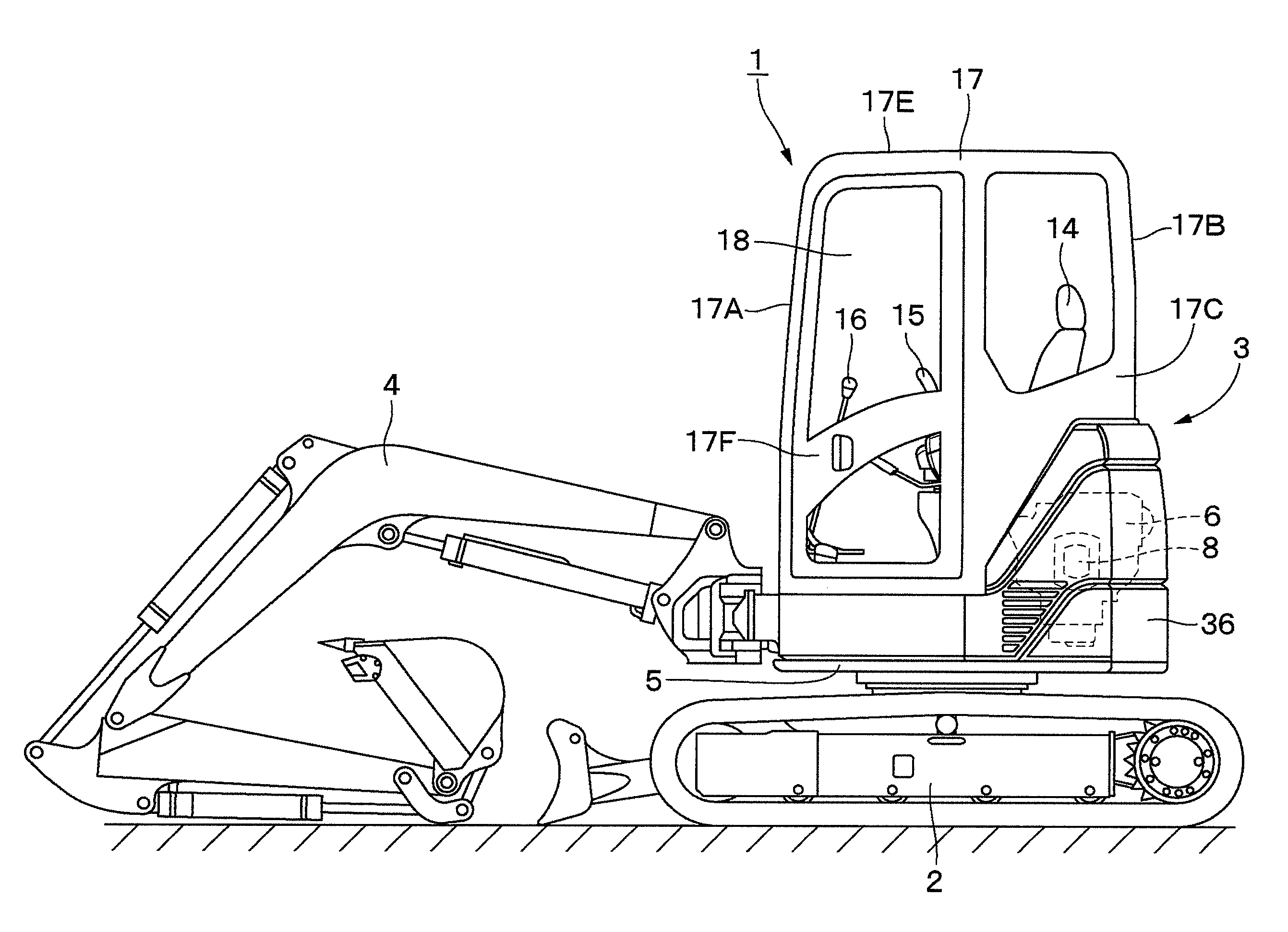
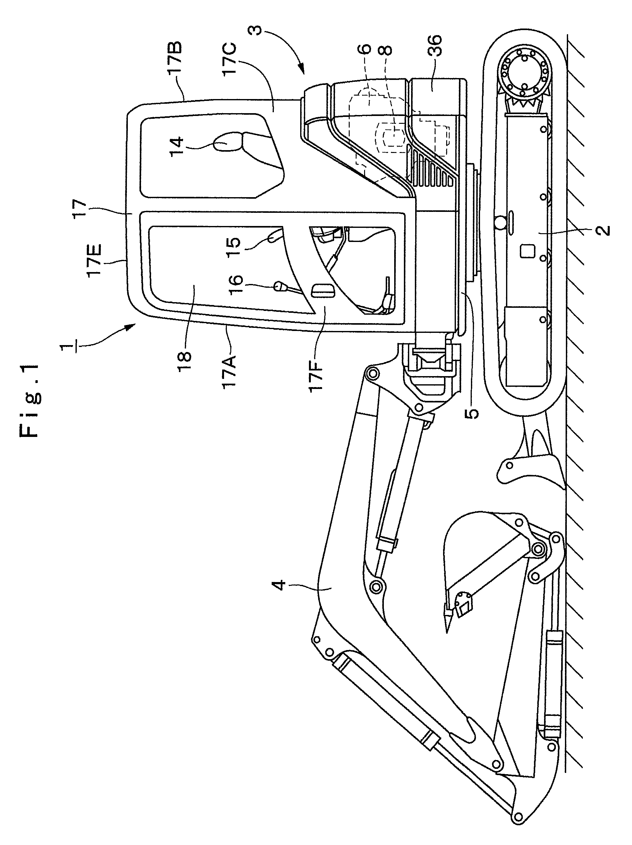
[0039]FIGS. 1 to 9 show a construction machine in accordance with a The characteristic of this embodiment lies in that the box body of the indoor unit is formed as a closed structure having a bottom surface, peripheral surfaces, and a top surface, and the indoor unit is arranged to be mounted in a state in which the top surface of the box body is opposed to a unit mounting surface of a footrest section.

[0040]In FIG. 1, designated at 1 is a hydraulic excavator of the cab specifications as a construction machine which is applied to this embodiment, and the hydraulic excavator 1 is a small-sized hydraulic excavator called a mini excavator which is suitable for operation in narrow work sites. The hydraulic excavator 1 is largely constituted by an automotive lower traveling structure 2, an upper revolving structure 3 which is swingably mounted on the lower traveling structure 2, and a working mechanism 4 provided on the front side in the front-rear direction of the upper revolving struc...

second embodiment

[0092]Designated at 43 is the indoor unit in accordance with the second embodiment which is provided on the footrest section 41. As shown in FIG. 15, this indoor unit 43 is largely constituted by the box body 44 for forming an outer shell, as well as the fan 25, the evaporator 26, the heater core 27, and the flow direction changing mechanism 28 which are provided in the box body 44.

[0093]The box body 44 in accordance with the second embodiment is formed by a rectangular bottom surface portion 44A extending in the left-right direction, as well as a front surface portion 44B, a rear surface portion 44C, a left side surface portion 44D, and a right side surface portion 44E which form peripheral surfaces extending upwardly from peripheries of the bottom surface portion 44A. Accordingly, the box body 44 is formed as a bottomed and top-open frame-like structure (casing) having a rectangular parallelepiped shape which, as a whole, is elongated in the left-right direction and is flattened i...


PUM


Abstract

An upper revolving structure (3) includes a revolving frame (5), a floor member (9) which is provided on the revolving frame (5) and a front side of which serves as a footrest section (11) on which an operator rests his or her feet, a cab box (17) which forms an operating room (18) above the floor member (9), and an indoor unit (23) disposed on the floor member (9) to supply sucked air as conditioned air. A lower surface (11B) side of the footrest section (11) of the floor member (9) is formed as a unit mounting surface (12), and, as for the indoor unit (23), a box body (24) is disposed on the lower side of the unit mounting surface (12) and, in this state, the box body (24) is mounted on the unit mounting surface (12) by means of a plurality of bolts (32).

Description

TECHNICAL FIELD[0001]The present invention relates to a construction machine such as a hydraulic excavator having an indoor unit on a floor member.BACKGROUND ART[0002]Generally, a hydraulic excavator as a construction machine is largely constituted by an automotive lower traveling structure, an upper revolving structure which is swingably mounted on the lower traveling structure, and a working mechanism liftably mounted on the front side of the upper revolving structure.[0003]The upper revolving structure is largely constituted by a revolving frame which forms a support structure; an engine provided on the rear side of the revolving frame to drive a hydraulic pump; a floor member provided on the revolving frame by being located on the front side of the engine, a rear side of which serves as an operator's seat mounting section for mounting an operator's seat, and a front side of which serves as a footrest section on which an operator rests his or her feet; a cab box provided so as to...

Claims


Application Information

Patent Timeline
Patent Type & Authority Patents(United States)
IPC IPC(8): E02F3/00B60H1/00E02F3/32E02F9/08E02F9/16
CPCE02F9/16B60H1/00378E02F9/0858E02F3/32E02F3/325E02F9/166B60H2001/00221E02F9/08
Inventor KIMURA, SHOGOTANAKA, TOMOYUKITABETA, HIROSHIISHII, HAJIME
Owner NIHON KENKI CO LTD
Why Eureka
Try Eureka