

Ultrasound and acoustophoresis for water purification
- Summary
- Abstract
- Description
- Claims
- Application Information
AI Technical Summary
Benefits of technology
Problems solved by technology
Method used
Image

Examples
example 1
Separation of Algae from Water Using an Acoustic Standing Wave
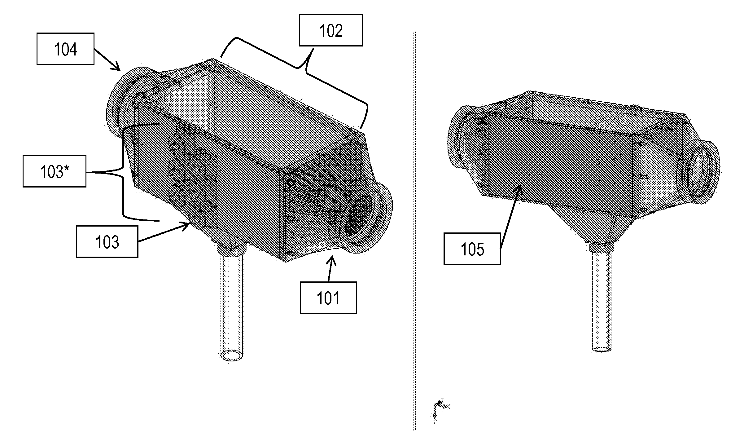
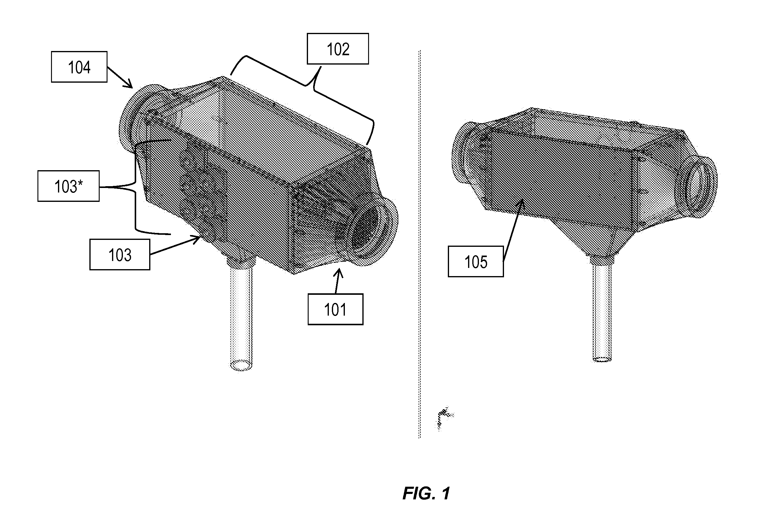
[0063]In an illustrative implementation, microorganisms including microalgae and bacterial spores were removed from a flowing water stream. As a demonstration of the current subject matter, algae of the halophilic Dunaliella Salina (similar in size and density to many pathogenic organisms) were grown in a bottle filled with salt water and placed under a grow light. The algae are removed from the bottle through tubes that pass them into a flow channel and past an acoustic transducer. The apparatus is shown in FIG. 1. The flow chamber was horizontal with the transducer on top facing downward. This resulted in a vertically oriented acoustic standing wave. The transducer used in the system of FIG. 1 is a PZT-4 2 MHZ transducer. Other transducers can be used.
[0064]The acoustic transducer was connected to an amplifier which receives its signal from a function generator and operates at about 15 Vrms in the current example. Once ...
example 2
Breaking Cell Wall and Cell Membranes of Microorganisms Using an Acoustic Standing Wave
[0065]Ultrasonic cavitation can be used to crush larger organisms (>10 microns). Some implementations of the current subject matter use high intensity ultrasound below an amplitude that causes cavitation. Breakage of cell walls and cellular membranes of microorganisms occurs due to the high pressures caused at the nodes of the acoustic standing wave. As an example of the potential of this approach, a suspension of concentrated microalgae of mixed sizes (mixed ages, 0.1 mm to 1.0 mm) of the nematode Caenorhabditis elegans were placed in a vertical glass tube with a PZT-4 2.3 MHz transducer mounted on the bottom with a glass plate on the top as the acoustic reflector. By simply subjecting the organisms to acoustophoresis without cavitation the smaller worms were crushed open and the larger organisms suffered catastrophic neuromuscular problems. This occurred when the pressure amplitude was about 0.5...
example 3
Separating Iron Oxide Particles from Water Using an Acoustic Standing Wave
[0067]The current subject matter can also concentrate and / or remove micron-scale metal oxide particles. As a demonstration of this capability, 10 micron iron oxide particles were suspended in water and passed through the apparatus shown in FIG. 3. In this demonstration, the flow chamber is horizontal with the transducer on top facing downward. The acoustic standing wave is in the vertical direction. The transducer is a PZT-4 2 MHZ transducer. A peristaltic pump is used to generate fluid flow rates that are most typically about 50 ml / min.
[0068]The acoustic transducer is connected to an amplifier which receives its signal from a function generator and operates at about 15 Vrms. Once the fluid flow and the acoustic transducer are turned on, trapping and concentration of iron oxide begins instantaneously or nearly instantaneously. The oxide particles are trapped in the acoustic field against the fluid drag force b...
PUM
| Property | Measurement | Unit |
|---|---|---|
| Size | aaaaa | aaaaa |
| Size | aaaaa | aaaaa |
| Size | aaaaa | aaaaa |
Abstract
Description
Claims
Application Information