Method for separating carbon dioxide

Inactive Publication Date: 2018-08-30
MITSUBISHI CHEM CORP
View PDF6 Cites 0 Cited by
  • Summary
  • Abstract
  • Description
  • Claims
  • Application Information

AI Technical Summary

Benefits of technology

[0013]According to the present invention, a method for separating carbon dioxide is as follows. In a separation membrane system provided with an inorganic separation membrane that is permeated by carbon dioxide preferentially from a mixed gas containing methane and the carbon dioxide, the carbon dioxide is membrane-separated from the mixed gas such that a carbon dioxide partial pressure difference ΔP at the final outlet on the carbon dioxide non-permeation side is

Problems solved by technology

Further, a separation membrane made of a polymer (hereinafter, also referred to as a “polymer membrane”), which has been used as a separation membrane, has a low separation performance, and has a problem in the chemical resistance and the like, therefore, in recent years, a membrane separation using an inorganic separation membrane, which is capable of performing a continuous operation, has a high separation performance, and is excellent in the chemical resistance, has been performed(for example, see JP 2012-236134 A).
On the other hand, when a membrane having a high separation performance such as an inorganic separation membrane is used, partial pressure of the carbon dioxide on the carbon dioxide permeation side is increased, and the partial pressure difference between on the carbon dioxide non-permeation side and on the permeation side is decreased when the mixed gas that is a raw materi

Method used


Image

  • Method for separating carbon dioxide
  • Method for separating carbon dioxide
  • Method for separating carbon dioxide

Examples


Example

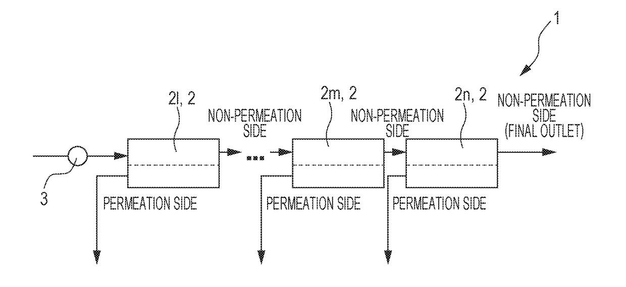
[0073]Hereinafter, as to one example of the embodiments of the present invention, a method for separating carbon dioxide according to the present invention will be described by using a separation membrane system 1 shown in FIG. 1. Further, in the equation (for example, Formula (I), and the like) mentioned in the present application, for convenience, the expression “·” (representing multiplying) may be omitted, such that “PX·XCO2” is expressed as “PXXCO2”.

[0074]FIG. 1 is a diagram showing a separation membrane system 1 in which a method for separating carbon dioxide according to the present invention is performed. The separation membrane system 1 shown in FIG. 1 shows a system in which an arbitrary number (stage) of single-kind inorganic separation membranes 2, which have an ideal separation factor (described later) common to each other, are arranged. Further, as a contact mode (flow model) of the gas flow on the high pressure side (non-permeation side) and the gas flow on the low pr...


PUM

PropertyMeasurementUnit
Partial pressureaaaaaaaaaa
Pressureaaaaaaaaaa
Mole fractionaaaaaaaaaa

Abstract

The present invention is a method for separating carbon dioxide in which the membrane separation is performed such that a carbon dioxide partial pressure difference ΔP at the final outlet on the carbon dioxide non-permeation side is ⅕ or more of the carbon dioxide partial pressure on the carbon dioxide non-permeation side (PX·XCO2), in a separation membrane system provided with an inorganic separation membrane that is permeated by carbon dioxide preferentially from a mixed gas containing methane and the carbon dioxide, therefore, the driving force that is a partial pressure difference of carbon dioxide between on the carbon dioxide non-permeation side and on the carbon dioxide permeation side is maintained, and further the membrane area of the inorganic separation membrane to be used can be suppressed smaller, the carbon dioxide can be efficiently separated, and the cost is low.

Description

CROSS REFERENCE TO RELATED APPLICATIONS[0001]The present application is a continuation under 35 U.S.C. § 120 of PCT / JP2016 / 081453, filed Oct. 24, 2016, which is incorporated herein reference and which claimed priority to Japanese Application No. 2015-213263, filed Oct. 29, 2015, the entire content of which is also incorporated herein by reference. The present application likewise claims priority under 35 U.S.C. § 119 to Japanese Application No. 2015-213263, filed Oct. 29, 2015, the entire content of which is also incorporated herein by reference.BACKGROUND OF THE INVENTION1. Field of the Invention[0002]The present invention relates to a method for separating carbon dioxide. More specifically, the present invention relates to a method for separating carbon dioxide, which is performed by a membrane separation using an inorganic separation membrane.2. Description of the Related Art[0003]As to the carbon dioxide (CO2) contained in a natural gas that includes methane (CH4) as the main co...

Claims


Application Information

Patent Timeline
IPC IPC(8): B01D53/22B01D71/02C10L3/10
CPCB01D53/22B01D71/02C10L3/104C10L2290/548B01D2253/108B01D2257/504B01D2258/05B01D69/02B01D71/028B01D2317/022B01D2325/20Y02C20/40
Inventor KAWAZUISHI, KENICHIIWAMURA, MASAYUKI
Owner MITSUBISHI CHEM CORP
Why Eureka
Try Eureka