Substrate processing method, substrate processing apparatus, and recipe selection method
Active Publication Date: 2021-06-03
SCREEN HLDG CO LTD
View PDF0 Cites 0 Cited by
Summary
Abstract
Description
Claims
Application Information
AI Technical Summary
This helps you quickly interpret patents by identifying the three key elements:
Problems solved by technology
Method used
Benefits of technology
Benefits of technology
The patent describes a method and apparatus for processing substrates with different surface regions. The method involves applying a processing liquid to the substrate surface, solidifying it to form a separation target film that covers the first removal target and a protective film covering the exposed region. The separation target film is then separated from the substrate surface using a stripping liquid, and the protective film is removed using a cleaning liquid. This allows for efficient removal of targets from the substrate surface. The method can provide improved results compared to other methods described in the patent.
Problems solved by technology
Therefore, when exposed substances are present in different regions on the surface of a substrate, there is a possibility that the removal targets will not be able to be sufficiently removed by forming a specific holding layer on the surface of the substrate and separating the holding layer from the surface of the substrate.
Method used
Image
Click on the blue label to locate the original text in one second.
Reading with bidirectional positioning of images and text.
Examples
first embodiment
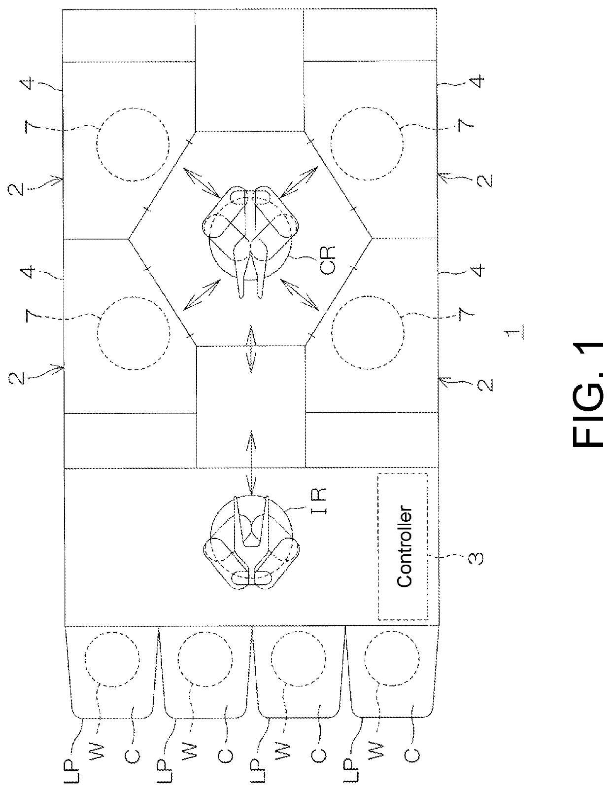
[0142]FIG. 1 is a schematic plan view showing a layout of a substrate processing apparatus 1 according to an embodiment of the disclosure.
[0143]The substrate processing apparatus 1 is a single-wafer type apparatus which processes substrates W such as silicon wafers one by one. In this embodiment, the substrate W is a disc-shaped substrate.
[0144]The substrate processing apparatus 1 includes a plurality of processing units 2 which processes the substrate W with a fluid, a load port LP on which a carrier C for accommodating a plurality of the substrates W processed by the processing unit 2 is placed, transfer robots IR and CR which transfer the substrate W between the load port LP and the processing unit 2, and a controller 3 which controls the substrate processing apparatus 1.
[0145]The transfer robot IR transfers the substrate W between the carrier C and the transfer robot CR. The transfer robot CR transfers the substrate W between the transfer robot IR and the processing unit 2. The ...
second embodiment
[0341]FIG. 11 is a schematic partial cross-sectional view showing a schematic configuration of a processing unit 2 provided in a substrate processing apparatus 1P according to a second embodiment. In FIG. 11, constituents equivalent to the constituents shown in FIGS. 1 to 10C described above are designated by the same reference numerals as those in FIG. 1 and the like, and the description thereof will be omitted. Similarly, in FIGS. 12 to 15E which will be described later, the same reference numerals as those in FIG. 1 and the like are provided, and the description thereof will be omitted.
[0342]Referring to FIG. 11, a main difference between the substrate processing apparatus 1P according to the second embodiment and the substrate processing apparatus 1 according to the first embodiment (refer to FIG. 3) is that in the substrate processing apparatus 1P according to the second embodiment, the substrate W subjected to a dry etching processing is subjected to the substrate processing.
[...
third embodiment
[0455]FIG. 17 is a schematic view of a first moving nozzle 9 and a third moving nozzle 11 of a processing unit 2 provided in a substrate processing apparatus 1Q according to a third embodiment of the disclosure, and members therearound. In FIG. 17, constituents equivalent to the constituents shown in FIGS. 1 to 16 described above are designated by the same reference numerals as those in FIG. 1 and the like, and the description thereof will be omitted. Similarly, in FIG. 18 which will be described later, the same reference numerals as those in FIG. 1 and the like are given, and the description thereof will be omitted.
[0456]Referring to FIG. 17, a main difference between the substrate processing apparatus 1Q according to the third embodiment and the substrate processing apparatus 1 according to the first embodiment (refer to FIG. 3) and the substrate processing apparatus 1P according to the second embodiment (refer to FIG. 11) is that in the substrate processing apparatus 1Q according...
PUM
Abstract
A substrate processing method includes a preprocessing forming step of forming a preprocessing film on a surface of a substrate having the surface on which a first region and a second region in which different substances are exposed are present, a preprocessing film separating step of separating the preprocessing film from the surface of the substrate with a stripping liquid, a processing film forming step of forming a processing film on the surface of the substrate after the preprocessing film separating step, and a processing film separating step of separating the processing film from the surface of the substrate with the stripping liquid. A removal capacity for the processing film to remove the first removal target present in the second region is higher than a removal capacity for the preprocessing film to remove the first removal target present in the second region, and a removal capacity for the preprocessing film to remove the first removal target present in the first region is higher than a removal capacity for the processing film to remove the first removal target present in the first region.
Description
CROSS-REFERENCE TO RELATED APPLICATIONS[0001]This application claims the priority benefits of Japanese Patent Application No. 2019-217610, filed on Nov. 29, 2019 and Japanese Patent Application No. 2019-217611, filed on Nov. 29, 2019. The entirety of the above-mentioned patent application is hereby incorporated by reference herein and made a part of this specification.BACKGROUND OF THE INVENTIONField of the Invention[0002]The disclosure relates to a substrate processing method and a substrate processing apparatus which process a substrate, and a recipeselection method which selects a recipe for carrying out the substrate processing method. For example, the substrates to be processed may include semiconductor wafers, liquid crystaldisplay device substrates, flat panel display (FPD) substrates for organic electroluminescence (EL) display devices or the like, optical disc substrates, magnetic disc substrates, magneto-optical disc substrates, photomask substrates, ceramic substrates, ...
Claims
Application Information
Patent Timeline
Application Date:The date an application was filed.
Publication Date:The date a patent or application was officially published.
First Publication Date:The earliest publication date of a patent with the same application number.
Issue Date:Publication date of the patent grant document.
PCT Entry Date:The Entry date of PCT National Phase.
Estimated Expiry Date:The statutory expiry date of a patent right according to the Patent Law, and it is the longest term of protection that the patent right can achieve without the termination of the patent right due to other reasons(Term extension factor has been taken into account ).
Invalid Date:Actual expiry date is based on effective date or publication date of legal transaction data of invalid patent.

