Refrigerant evaporator

a technology of refrigerant evaporator and bottom plate, which is applied in the direction of refrigeration components, indirect heat exchangers, lighting and heating apparatus, etc., can solve the problems that refrigerant evaporator is not suited to installation on the bottom plate of the casing of an outdoor unit or the like of an air conditioning apparatus

Active Publication Date: 2017-08-17
DAIKIN IND LTD
View PDF9 Cites 11 Cited by
  • Summary
  • Abstract
  • Description
  • Claims
  • Application Information

AI Technical Summary

Benefits of technology

[0012]Here, the refrigerant can be kept from becoming easier to be introduced to the second flat tube out of the flat tubes communicating with the lowermost-tier supply space in the refrigerant supply section, and the refrigerant in the gas-liquid mixed state flowing to the flat tubes communicating with the lowermost-tier supply space can be equalized.

Problems solved by technology

In the above conventional refrigerant distributor, a structure that introduces the refrigerant from the lower end lower surface is employed from the standpoint of ensuring the ability to distribute the refrigerant, but a refrigerant evaporator including the refrigerant distributor must be disposed in a high position in correspondence to introducing the refrigerant from the lower end lower surface, and because of this, the refrigerant evaporator is not suited to installation on a bottom plate of a casing of an outdoor unit or the like of an air conditioning apparatus.

Method used


Image

  • Refrigerant evaporator
  • Refrigerant evaporator
  • Refrigerant evaporator

Examples


Embodiment Construction

[0043]An embodiment of a refrigerant evaporator pertaining to the present invention and example modifications thereof will be described below on the basis of the drawings. It should be noted that the specific configurations of the refrigerant evaporator pertaining to the present invention are not limited to those in the following embodiment and the example modifications thereof, and can be changed to the extent that they do not depart from the spirit of the invention.

(1) Overall Configuration of Air Conditioning Apparatus

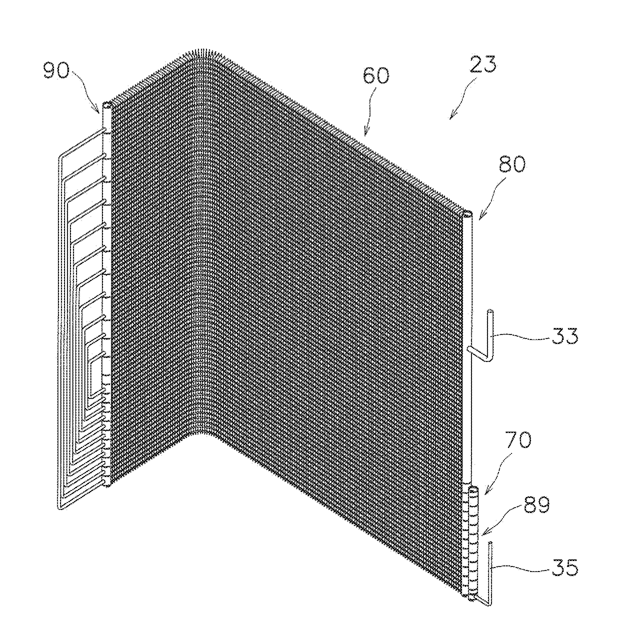
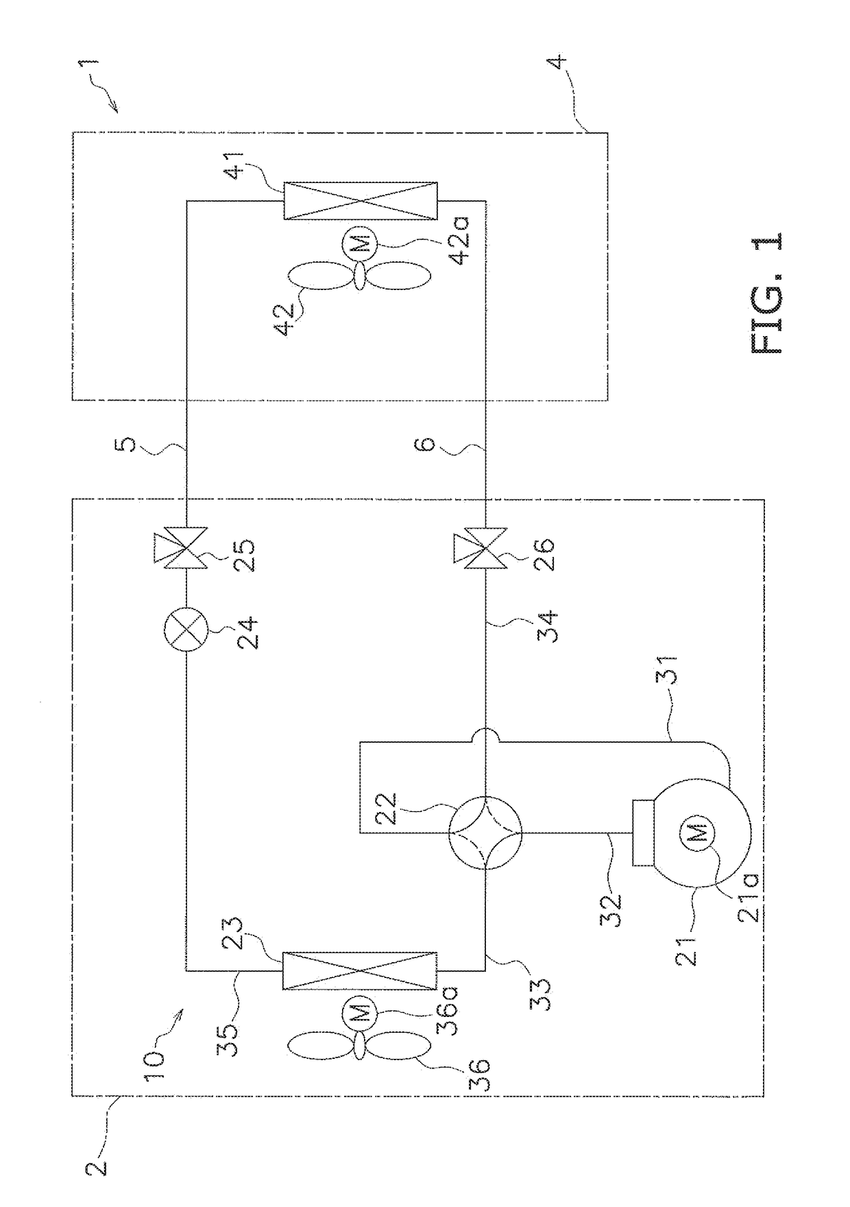
[0044]FIG. 1 is a general configuration diagram of an air conditioning apparatus 1 having an outdoor heat exchanger 23 serving as the refrigerant evaporator pertaining to the embodiment of the present invention.

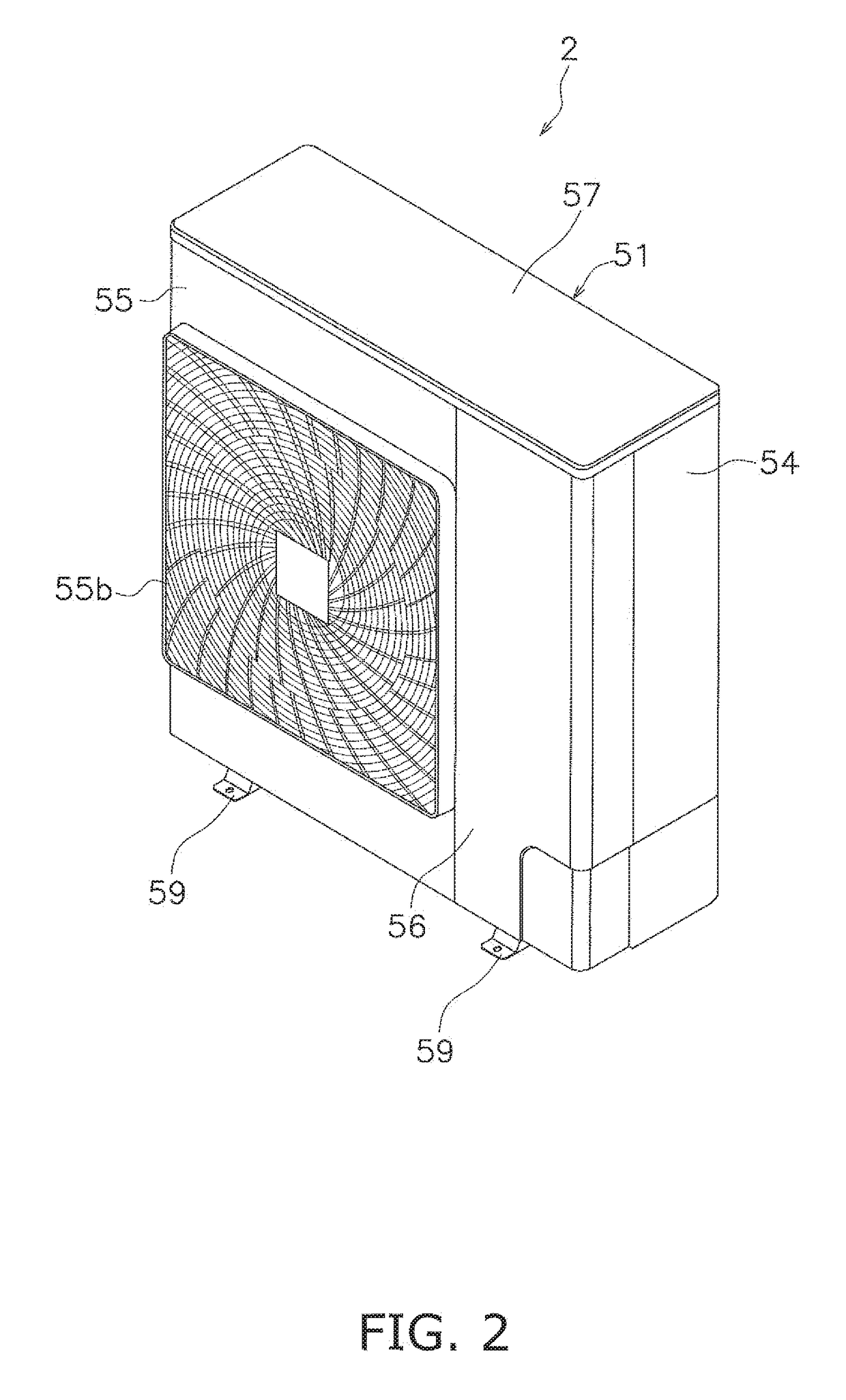
[0045]The air conditioning apparatus 1 is an apparatus capable of cooling and heating a room in a building or the like by performing a vapor compression refrigeration cycle. The air conditioning apparatus 1 is configured as a result of mainly an outdoor unit ...


PUM


Abstract

A refrigerant evaporator includes a plurality of vertically disposed flat tubes, and a refrigerant distribution and supply section that causes inflowing refrigerant to flow out to the plurality of flat tubes on a downstream side. The refrigerant distribution and supply section includes a refrigerant supply section having plural supply spaces, a refrigerant introduction and distribution section having an introduction space to introduce the inflowing refrigerant from a lower end side surface, and a distribution space to distribute the refrigerant, and plural connecting passages that guide the refrigerant to the supply spaces. A first flat tube communicating with a lowermost-tier supply space positioned on the lowermost side is disposed at a height position included in a height range of the introduction space, and a lowermost-tier connecting passage that guides the refrigerant to the lowermost-tier supply space is disposed at a position higher than the introduction space.

Description

TECHNICAL FIELD[0001]The present invention relates to a refrigerant evaporator, and particularly a refrigerant evaporator equipped with plural flat tubes disposed along the vertical direction and a refrigerant distributor that causes inflowing refrigerant to flow out to the plural flat tubes on the downstream side.BACKGROUND ART[0002]Conventionally, as described in patent document 1 (JP-A No. 2011-231972), there have been plural refrigerant outflow tubes (flat tubes) disposed along the vertical direction and a refrigerant distributor (a refrigerant distribution and supply section) that causes inflowing refrigerant to flow out to the plural refrigerant outflow tubes (flat tubes) on the downstream side. In this refrigerant distributor, the inflowing refrigerant is introduced from a lower end lower surface and caused to flow out to the plural refrigerant outflow tubes on the downstream side.SUMMARY OF INVENTION[0003]In the above conventional refrigerant distributor, a structure that in...

Claims


Application Information

Patent Timeline
Patent Type & Authority Applications(United States)
IPC IPC(8): F25B39/00F28F9/02
CPCF25B39/00F28F9/0204F25B39/028F28F9/0273F28F9/0243F28F9/028F28F9/02F28F9/22F28D1/053F25B13/00
Inventor JINDOU, MASANORIORITANI, YOSHIOSAKAMAKI, TOMOHIKOHAMADATE, JUNICHI
Owner DAIKIN IND LTD
Why Eureka
Try Eureka