Carbon nanotube composite structure and method of manufacturing the same

a carbon nanotube and composite structure technology, applied in the field of carbon nanotube structure, can solve the problems of insufficient utilization of mechanical strength of carbon nanotube intrinsically, inability to obtain intended characteristics, and inability to achieve the desired characteristics, etc., to achieve the effect of reducing the length of the cross-linked site between the carbon nanotubes and stable chemical structur

Inactive Publication Date: 2005-03-31
FUJIFILM BUSINESS INNOVATION CORP
View PDF3 Cites 79 Cited by
  • Summary
  • Abstract
  • Description
  • Claims
  • Application Information

AI Technical Summary

Benefits of technology

[0054] From the above, the size of the cross-linked site, which bonds the carbon nanotubes together, becomes constant depending on the functional group to be bonded. A carbon nanotube has an extremely stable chemical structure, so that a possibility of bonding of functional groups or the like excluding the functional groups intended for a modification, is low. When chemically bonding the functional groups together, the designed structure of the cross-linked site can be obtained, providing a homogeneous carbon nanotube structure.
[0055] Further, functional groups are chemically bonded together and thus the length of the cross-linked site between the carbon nanotubes can be shortened compared to the case of cross-linking the functional groups together using a cross-linking agent. Therefore, the carbon nanotube structure becomes dense, and effects peculiar to carbon nanotubes are easily obtained.

Problems solved by technology

Therefore, it becomes difficult to obtain intended characteristics of the resultant carbon nanotube structure, which places limitations on the use of the resultant carbon nanotube structure in various applications.
In addition, a network structure of carbon nanotubes is not formed sufficiently densely, so that there arises a problem in that excellent characteristics including electric conductivity, thermal conductivity, and a mechanical strength which a carbon nanotube intrinsically has can not be sufficiently utilized.

Method used


Image

  • Carbon nanotube composite structure and method of manufacturing the same
  • Carbon nanotube composite structure and method of manufacturing the same
  • Carbon nanotube composite structure and method of manufacturing the same

Examples


example

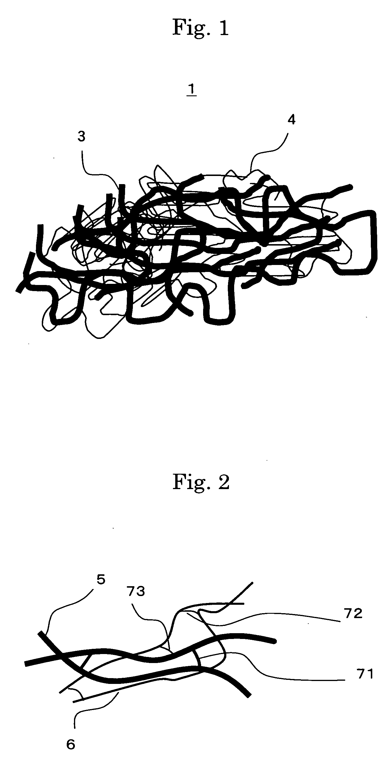
[0179] [Carbon Nanotube Composite Structure Using Glycerin-Cross-Linked Multi-Wall Carbon Nanotube Structure and Single-wall Carbon Nanotube Structure]

[0180] (First Addition Step)

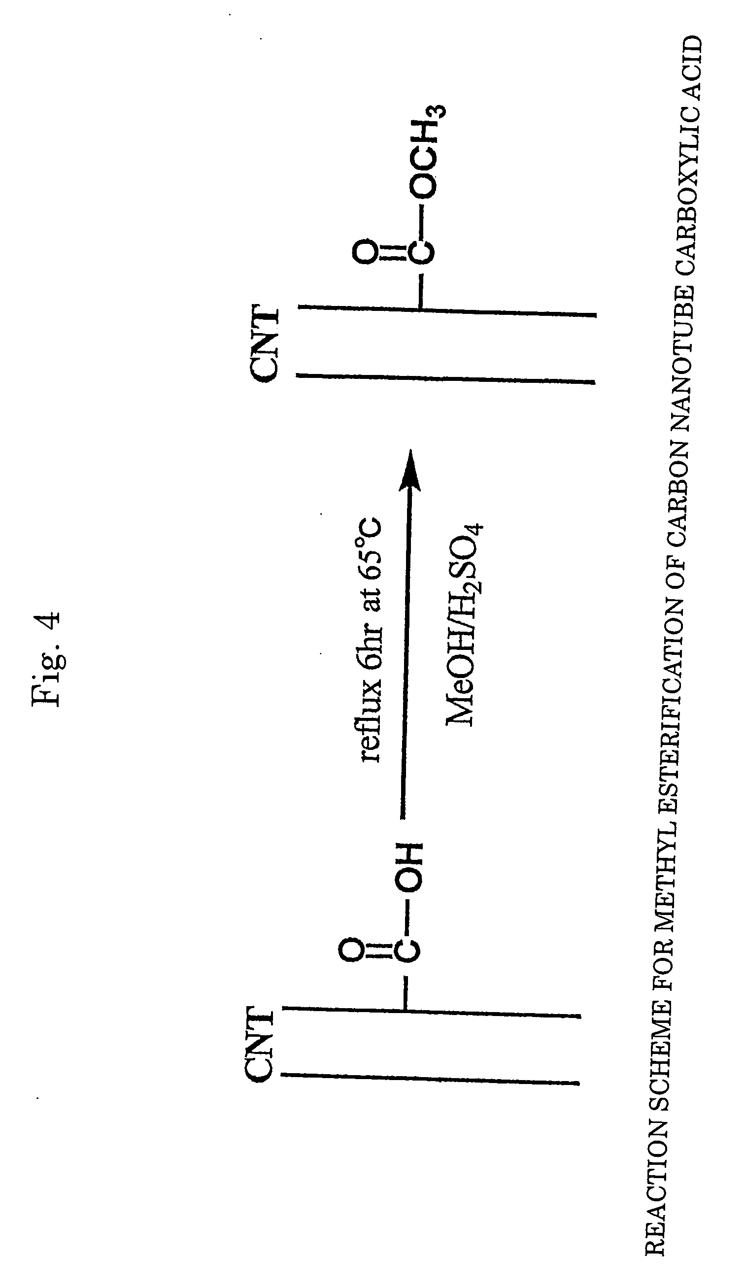
[0181] 30 mg of multi-layer carbon nanotube powder (purity: 90%, average diameter: 30 nm, average length: 3 μm, available from Science Laboratory Inc.) was added to 20 ml of concentrated nitric acid (a 60 mass % aqueous solution, available from KANTO KAGAKU) for reflux at 120?C for 20 hours to synthesize a carbon nanotube carboxylic acid. A reaction scheme of the above is shown in FIG. 3. In FIG. 3, a carbon nanotube (CNT) portion is represented by two parallel lines (same applies for other figures relating to reaction schemes).

[0182] The temperature of the solution was returned to room temperature, and the solution was centrifuged at 5,000 rpm for 15 minutes to separate a supernatant liquid from a precipitate. The recovered precipitate was dispersed in 10 ml of pure water, and the dispersion liquid was s...


PUM

PropertyMeasurementUnit
diameteraaaaaaaaaa
Young's moduliaaaaaaaaaa
diameteraaaaaaaaaa

Abstract

Provided are a carbon nanotube structure more excellent in electric conductivity, thermal conductivity, and mechanical strength, and a method of manufacturing the carbon nanotube structure. A carbon nanotube composite structure is characterized by including: a first carbon nanotube structure in which functional groups bonded to plural carbon nanotubes are chemically bonded and mutually cross-linked to construct a network structure; and a second carbon nanotube structure in which functional groups bonded to plural carbon nanotubes are chemically bonded and mutually cross-linked to construct a network structure, the second carbon nanotube structure being combined with the network structure of the first carbon nanotube structure.

Description

FIELD OF THE INVENTION AND RELATED ART STATEMENT [0001] The present invention relates to a carbon nanotube structure and a method of manufacturing the same. [0002] Carbon nanotubes (CNTs), with their unique shapes and characteristics, are being considered for various applications. A carbon nanotube has a tubular shape of one-dimensional nature which is obtained by rolling one or more graphene sheets composed of six-membered rings of carbon atoms into a tube. A carbon nanotube which is formed from one graphene sheet is called a single-wall nanotube (SWNT) while a carbon nanotube which is formed from plural graphene sheets is called a multi-wall nanotube (MWNT). SWNTs are about 1 nm in diameter whereas multi-wall carbon nanotubes measure several tens nm in diameter, and both are far thinner than their predecessors, which are called carbon fibers. [0003] One of the characteristics of carbon nanotubes resides in that the aspect ratio of length to diameter is very large since the length ...

Claims


Application Information

Patent Timeline
Patent Type & Authority Applications(United States)
IPC IPC(8): B82B3/00B82B1/00C01B31/02D02G3/00
CPCB82B3/00Y10T428/2913B82Y40/00B82Y30/00
Inventor WATANABE, MIHOMANABE, CHIKARASHIGEMATSU, TAISHIANAZAWA, KAZUNORIISOZAKI, TAKASHIKISHI, KENTAROHIRAKATA, MASAKIOOMA, SHIGEKIOKADA, SHINSUKEWATANABE, HIROYUKI
Owner FUJIFILM BUSINESS INNOVATION CORP
Why Eureka
Try Eureka