Surface-mount type crystal oscillator

a crystal oscillator and surface mount technology, applied in piezoelectric/electrostrictive/magnetostrictive devices, oscillator generators, semiconductor devices, etc., can solve the problems of difficult to reduce the height of the crystal oscillator to less than 0.5 mm, and the above-described surface-mount type crystal oscillator is unsuitable for the sim card, so as to achieve the effect of reducing the height dimension of the surface-mount type and being easy to measur

Inactive Publication Date: 2009-08-20
NIHON DEMPA KOGYO CO LTD
View PDF7 Cites 11 Cited by
  • Summary
  • Abstract
  • Description
  • Claims
  • Application Information

AI Technical Summary

Benefits of technology

[0022]An object of the present invention is to provide a surface-mount type crystal oscillator in which an IC chip and a crystal blank are arranged on an inner bottom surface of a recess of a container body and in a horizontal direction, thus reducing the height dimension of the crystal oscillator and facilitating abutment of a probe against inspection terminals.
[0024]In this configuration, the crystal blank and the IC chip are accommodated in the separate recesses. This eliminates the need to encapsulate the IC chip per se with a metal cover. A height from a top surface of the bottom wall to a surface of the IC chip which is different from a circuit forming surface depends basically on the thickness of the IC chip. If the IC chip is secured to the container body using ultrasonic thermocompression bonding, the height is equal to the sum of the thickness of the IC chip and the diameter of a bump. For the thickness of the crystal oscillator at a position where the second recess is formed, the thickness of the metal cover, the distance between the metal cover and the IC chip, and the like need not be taken into account. As a result, the maximum thickness of the crystal oscillator depends on the thickness thereof at the first recess. The crystal blank is hermetically encapsulated in the first recess using the metal cover. The thickness of the crystal blank depends on the vibration frequency thereof but is generally smaller than that of the IC chip. Therefore, the present invention enables a reduction in the height dimension of the surface-mount type crystal oscillator compared to the conventional one.
[0025]Furthermore, the inspection terminal is provided on the top surface of the frame wall in the area around the second recess. The present invention thus allows vibration characteristics of the crystal blank, serving as the crystal unit, to be easily measured.

Problems solved by technology

The above-described surface-mount type crystal oscillators are unsuitable for the SIM card, which needs to be about 0.5 mm or less in height.
However, either with the wire bonding or using the bumps, the conventional technique has difficulty in reducing the height of the crystal oscillator to less than 0.5 mm.

Method used


Image

  • Surface-mount type crystal oscillator
  • Surface-mount type crystal oscillator
  • Surface-mount type crystal oscillator

Examples


first embodiment

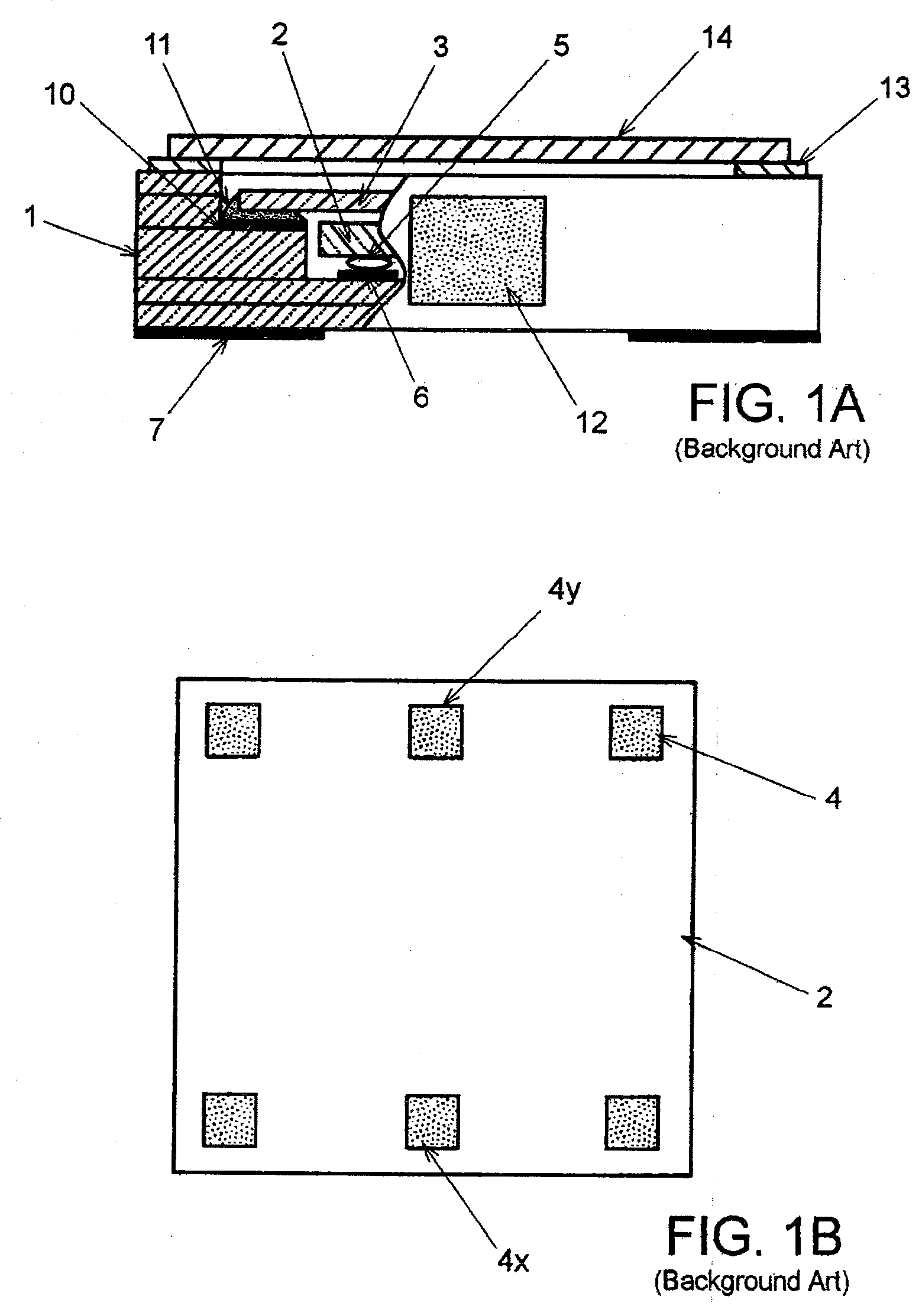
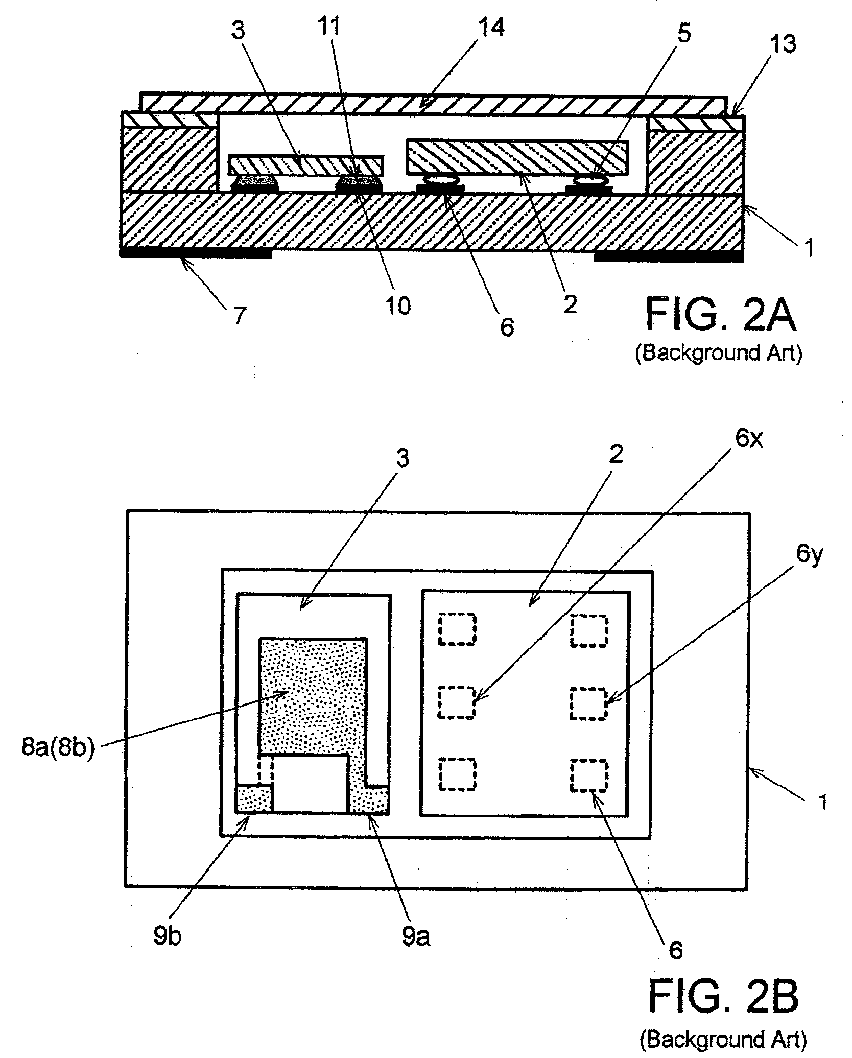
[0039]In FIGS. 3A, 3B, and 3C showing a surface-mount type temperature compensated crystal oscillator according to the present invention, the same components as those in FIGS. 1A, 1B, 2A, and 2B are denoted by the same reference numerals. Duplicate descriptions will not be repeated.

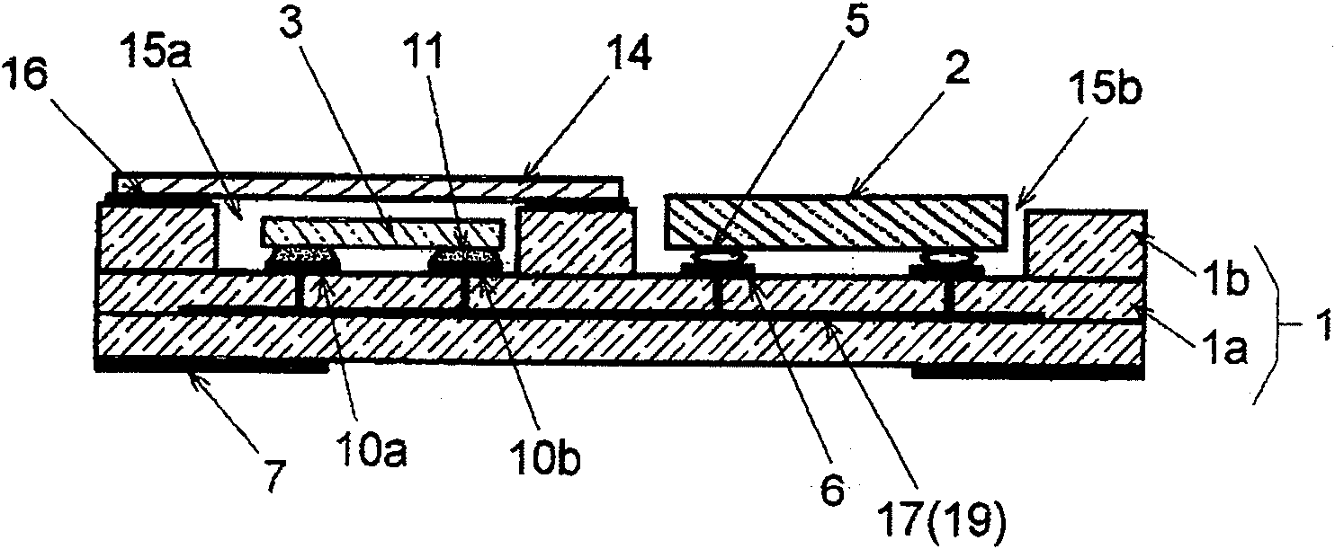
[0040]In the crystal oscillator according to the present embodiment, IC chip 2 and quartz crystal blank 3 are mounted in container body 1 made up of laminated ceramics, as is the case with the crystal oscillator shown in FIGS. 2A and 2B. Container body 1 is configured such that frame wall 1b is laminated on bottom wall 1a which has a generally rectangular, flat plate shape. Bottom wall 1a is composed of two ceramic layers. Two generally rectangular openings are formed in juxtaposition in frame wall 1b. The openings form first recess 15a and second recess 15b in one principal surface of container body 1. The planar outside dimension of container body 1 is, for example, 3.2 mm×2.5 mm, which is a de facto st...

third embodiment

[0054]In the third embodiment, the frame width of frame wall 1b is larger on one side of second recess 15b with IC chip 2 accommodated therein than on the other sides thereof. For example, frame width W1 on a lower side, in FIG. 6, of second recess 15b is set to be larger than frame width W in other regions. In particular, frame width W1 on the lower side, in FIG. 6, of second recess 15b is larger than the frame width at a position where frame wall 1b surrounds first recess 15a. A pair of inspection terminals 18a, 18b are formed in an area of the top surface of frame wall 1b which has frame width W1. Thus, the increased frame width allows the size of inspection terminals 18a, 18b to be further increased. This enables a probe to be more reliably contacted with inspection terminals 18a, 18b.

[0055]A surface-mount type temperature compensated crystal oscillator according to a fourth embodiment of the present invention will be next described FIGS. 7A and 7B show the respective crystal o...


PUM


Abstract

A surface-mount type crystal oscillator includes: a container body with a first recess and a second recess; a crystal blank including excitation electrodes on respective principal surfaces thereof and hermetically encapsulated in the first recess; and an IC chip which is accommodated in the second recess and into which at least an oscillation circuit using the crystal blank is integrated. The container body includes a bottom wall and a frame wall provided on the bottom wall. Two openings which make up the first and second recesses, respectively, are formed in juxtaposition in the frame wall. A pair of inspection terminals are provided in an area of a top surface of the frame wall which surrounds the second recess. The inspection terminals are electrically connected to the excitation electrodes of the crystal blank.

Description

BACKGROUND OF THE INVENTION[0001]1. Field of the Invention[0002]The present invention relates to a surface mount type quartz crystal oscillator with a reduced height dimension, and in particular, to a surface mount type crystal oscillator mounted in a thin electronic card or a smart card such as a SIM (Subscriber Identify Module) card, a PC (Personal Computer) card, or an IC (Integration Circuit) card.[0003]2. Description of the Related Arts[0004]An SIM card, used in a cellular phone, is a typical example of an electronic card composed of a small card containing a memory device and an IC chip. The SIM card stores authentication information and the like for the cellular phone and is used to store use permission information for the cellular phone and personal information such as a telephone number. In recent years, efforts have been made to incorporate a GPS (Global Positioning System) function into the SIM card. In this case, a precise frequency reference signal needs to be supplied ...

Claims


Application Information

Patent Timeline
Patent Type & Authority Applications(United States)
IPC IPC(8): H03B1/00
CPCH03H9/0514H03H9/0519H01L2224/16225H03H9/1014H03H9/1021H03H9/0542
Inventor TAKEUCHI, TOSHIAKISUGAWARA, KENICHIMORIYA, KOUICHI
Owner NIHON DEMPA KOGYO CO LTD
Why Eureka
Try Eureka