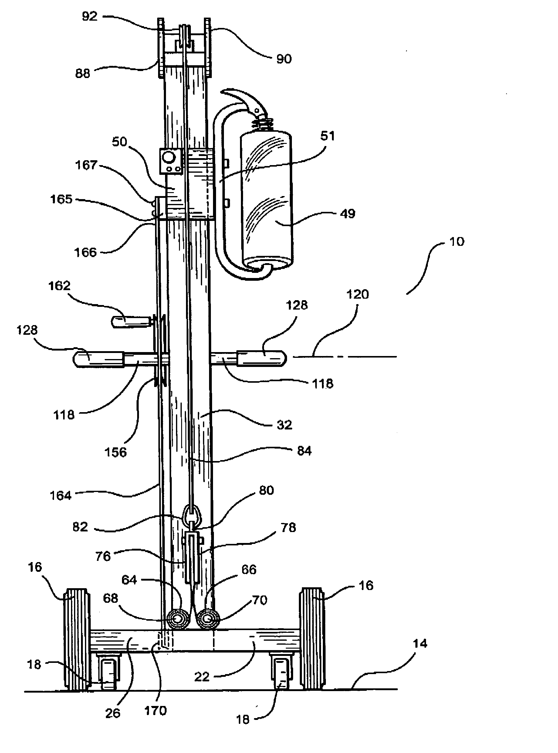
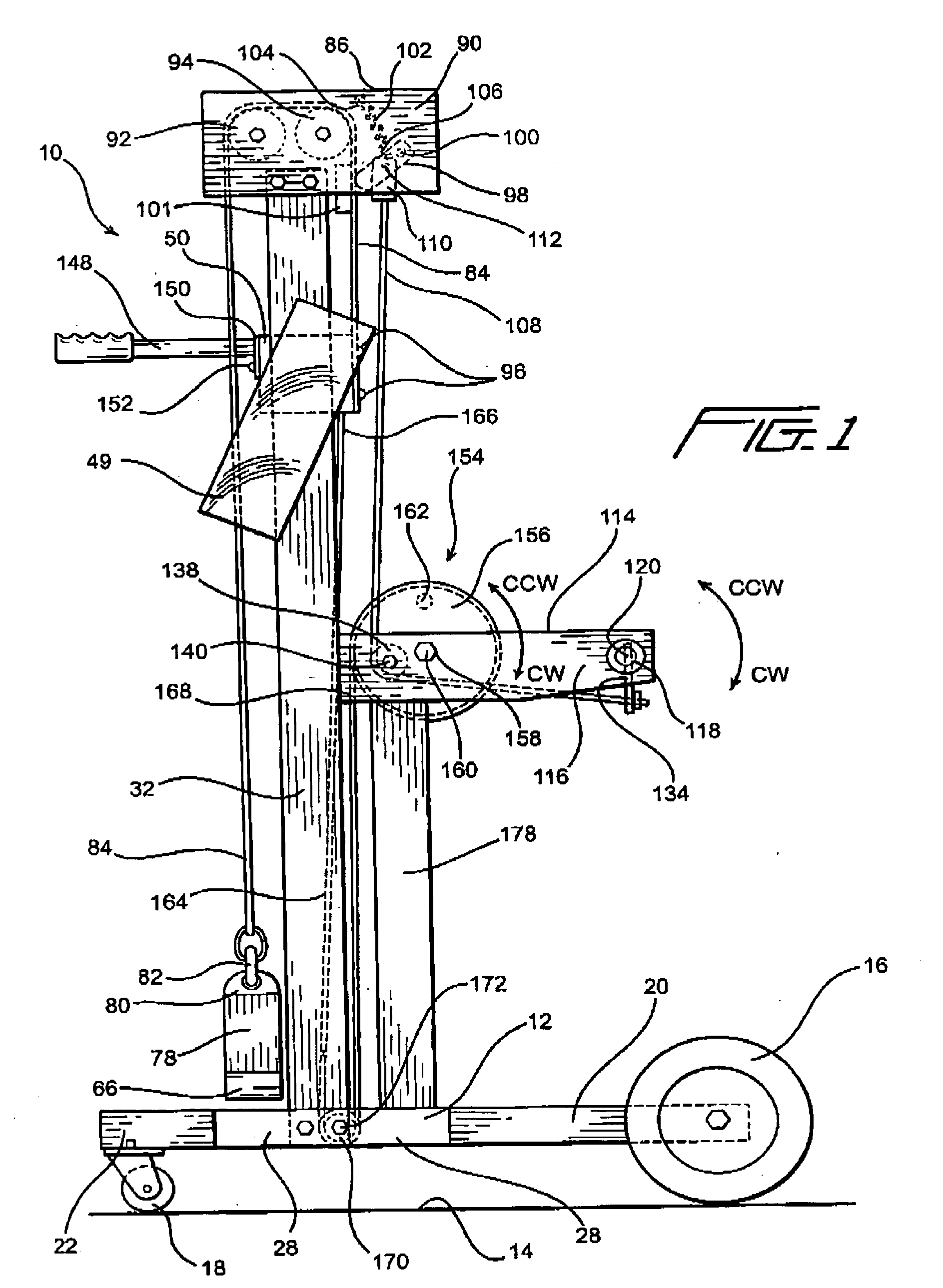
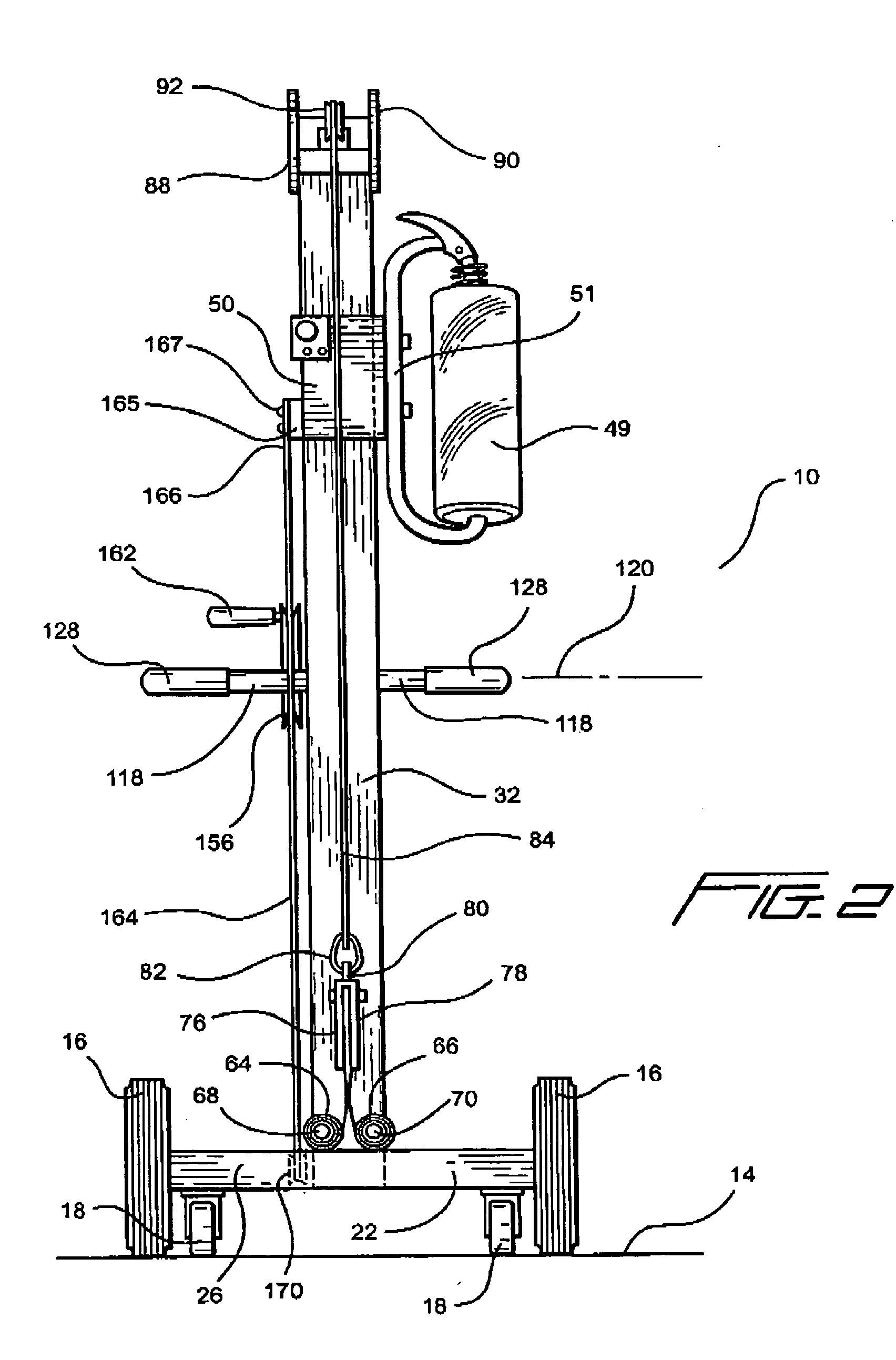
[0009] Another object of the present invention is to provide a new and improved portable plastic film wrapping apparatus or system for applying wrapping or packaging film to palletized loads or products wherein the various operational drawbacks and disadvantages, characteristic of PRIOR ART apparatus, systems, or methods of operating the same, are effectively overcome.
[0010] An additional object of the present invention is to provide a new and improved portable plastic film wrapping apparatus or system for applying wrapping or packaging film to palletized loads or products wherein as a result of the vertical movements of the film roll carriage of the film wrapping apparatus or system, along the vertical mast member, no longer being controlled by means of a counterweight mechanism but, to the contrary, being controlled by means of a negator spring assembly, the vertical mast member no longer needs to house or accommodate a counterweight mechanism whereby the height dimension of the vertical mast member can be substantially reduced.
[0011] A further object of the present invention is to provide a new and improved portable plastic film wrapping apparatus or system for applying wrapping or packaging film to palletized loads or products wherein as a result of the vertical movements of the film roll carriage of the film wrapping apparatus or system, along the vertical mast member, no longer being controlled by means of a counterweight mechanism but, to the contrary, being controlled by means of a negator spring assembly, the vertical mast member no longer needs to house or accommodate a counterweight mechanism whereby the height dimension of the vertical mast member can be substantially reduced such that destabilizing moment arms or forces are effectively eliminated so as to permit operator personnel to easily control the film wrapping apparatus or system during the film wrapping or packaging operation, and wherein, further, the width dimension of the apparatus or system can likewise be substantially reduced in view of the fact that the destabilizing moment arms or forces have been eliminated.
[0012] A last object of the present invention is to provide a new and improved portable plastic film wrapping apparatus or system for applying wrapping or packaging film to palletized loads or products wherein as a result of the vertical movements of the film roll carriage of the film wrapping apparatus or system, along the vertical mast member, no longer being controlled by means of a counterweight mechanism but, to the contrary, being controlled by means of a negator spring assembly, the vertical movements of the film roll carriage are not subjected to accelerated movements which would otherwise result in variable speeds of descent, and in addition, vertically movements of the film roll carriage may be achieved in an infinitely controlled manner. SUMMARY OF THE INVENTION
[0014] Accordingly, if continuous spiral wrapping of the palletized load or product is desired to be achieved while the operator walks, and simultaneously steers the apparatus or system, around the palletized load disposed at the wrapping
station, the operator simply needs to actuate the control cable so as to effectively cause the pawl mechanism to be released from its engaged position with respect to the lift cable whereby the recoiling of the pair of negator springs will serve to elevate the film roll carriage at a
constant rate of speed such that uniform wrapping of the palletized load or product within the packaging or wrapping film is able to be achieved. Alternatively, if continuous concentric wrapping of the palletized load or product within the packaging or wrapping film at a particular elevational level is desired, which is known as reinforcing wrapping, the control cable is not actuated whereby the pawl mechanism is maintained engaged with the lift cable such that further elevation of the film roll carriage, and the roll of wrapping film mounted thereon, is effectively prevented. At the completion of a wrapping cycle or operation, the operator can use either one of two alternative means for moving the film roll carriage in a downward mode from its elevated position, back toward its lowered START position, which effectively disengages the pawl mechanism from the lift cable and simultaneously causes the pair of negator springs to again be uncoiled in preparation for a subsequent palletized load or product film packaging or wrapping operation or cycle. The apparatus or system of the present invention also permits several operative components thereof to effectively be reversed whereby in lieu of the film roll carriage being elevated during a film-wrapping operation or cycle wherein the palletized load or product is normally wrapped in a direction proceeding upwardly from the bottom of the load or product, the film roll carriage can descend during a film-wrapping operation or cycle wherein the palletized load or product is wrapped in a direction proceeding downwardly from the top of the load or product.


