Rain diverter

Active Publication Date: 2016-01-19
JOHNSON DANIEL JOHN +1
View PDF20 Cites 1 Cited by
  • Summary
  • Abstract
  • Description
  • Claims
  • Application Information

AI Technical Summary

Benefits of technology

[0011]An object of the present invention is to address the need for a rainwater diverter for a building structure. Advantageously, embodiments of the present disclosure describe a rainwater diverter that can be easily installed as well as rem

Problems solved by technology

Rainwater run-off from roofing and other surfaces, including overflow from gutters, downspouts, drainpipes, and other water-handling channels can cause appreciable erosion and other water-related damage to the interior and exterior of a building structure.
Unless properly directed away from the building foundation, rainwater run-off can collect or flow around the sides of a house or other structure, leaking into basement areas, degrading above- and below-ground portions of the foundation, forming pits and holes and washing away soil and plants, and causing unpleasant or even unsafe conditions for those in and around the building.
As is well known, each type of solution that has been developed for handling this problem faces a number of limitations.
Splash blocks, for example, are often quite heavy and can obstruct easy building access.
With heavy rainfall, splash blocks can be ineffective, allowing splash-over or simply redirecting excess water for pooling at some alternate location.
Downspout extensions, although helpful in some situations, typically require regular maintenance to prevent clogging and can present a tripping hazard for those walking near the structure.
Neither splash blocks nor downspout extensions spread the rainwater over a broad angular span; instead, the run-off often tends to pool in low areas or to cause erosion in some cases.
Outside corners of a building are pa

Method used


Image

  • Rain diverter
  • Rain diverter
  • Rain diverter

Examples


Example

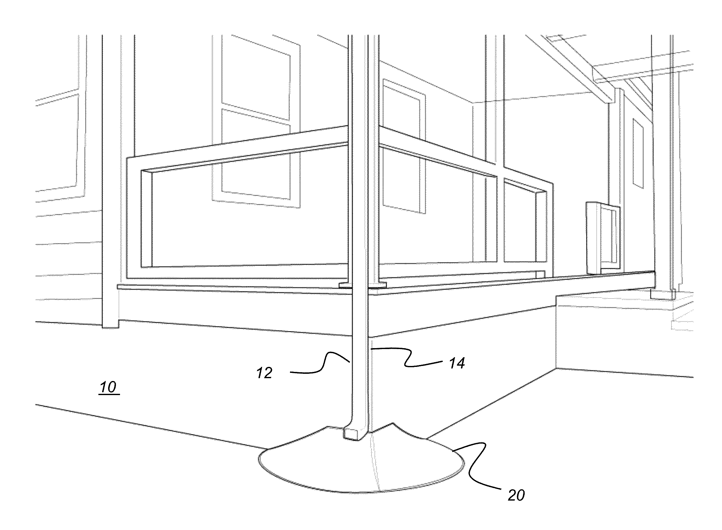
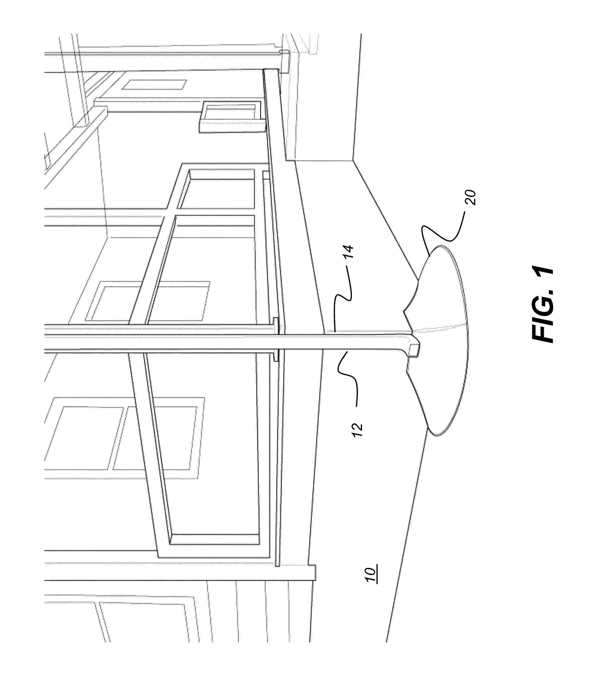
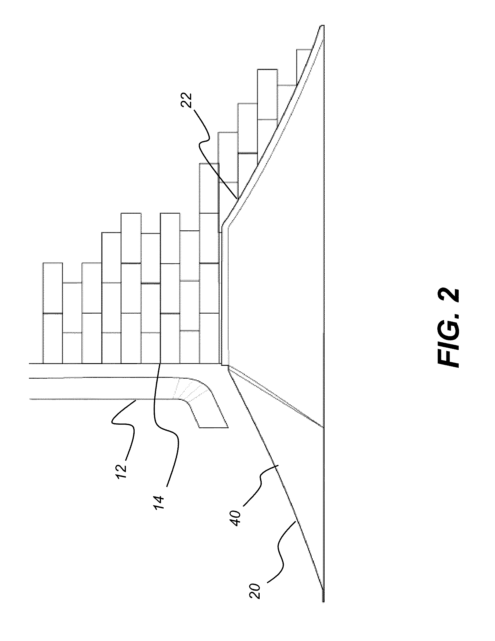
[0031]The following is a detailed description of the preferred embodiments of the invention, reference being made to the drawings in which the same reference numerals identify the same elements of structure in each of the several figures.

[0032]Where they are used, the terms “first”, “second”, and so on, do not necessarily denote any ordinal or priority relation, but may be used for more clearly distinguishing one element or time interval from another.

[0033]The term “exemplary” indicates that the description is used as an example, rather than implying that it is an ideal.

[0034]In the context of the present disclosure, the term “unitary” has its standard connotation meaning formed in a single piece or unit.

[0035]The term “orthogonal” or “substantially orthogonal” describes a relationship of two structures that are at a 90 degree (+ / −6 degree) angle with relation to each other.

[0036]In the context of the present disclosure, the term “rigid” is used to indicate a structure with sufficie...


PUM


Abstract

A rainwater diverter shell has edge flashing with a right-angled flange formed by a first upper flange that defines a first vertical plane and a second upper flange that defines a second vertical plane orthogonal to the first. A first side flange extends between the first upper flange and a base and has a first side flange surface in parallel to the first vertical plane. A second side flange extends between the second upper flange and the base and has a second side flange surface in parallel to the second vertical plane. A horizontal base flange defines a base plane. The horizontal base flange extends along an arc that subtends a reflex angle between the first and second vertical planes. A sloped surface descends from the edge flashing to the horizontal base flange and extends across the rainwater diverter from the first side flange to the second side flange.

Description

CROSS REFERENCE TO RELATED APPLICATIONS[0001]The present application claims priority from U.S. Ser. No. 62 / 046,611 entitled “RAIN DIVERTER” and filed as a provisional patent application on Sep. 5, 2014 in the name of Daniel John Johnson et al., incorporated herein in its entirety.FIELD OF THE INVENTION[0002]The invention relates generally to drainage apparatus and methods for diverting rainwater away from a structure and more particularly relates to a rain diverter that redirects rainwater run-off from an exterior corner of a structure.BACKGROUND OF THE INVENTION[0003]Rainwater run-off from roofing and other surfaces, including overflow from gutters, downspouts, drainpipes, and other water-handling channels can cause appreciable erosion and other water-related damage to the interior and exterior of a building structure. Unless properly directed away from the building foundation, rainwater run-off can collect or flow around the sides of a house or other structure, leaking into baseme...

Claims


Application Information

Patent Timeline
IPC IPC(8): E02D31/06E04B1/64E03B7/07
CPCE02D31/06E04B1/64E03B7/07E04D13/08E04D2013/0813
Inventor JOHNSON, DANIEL JOHNCOLAPRETE, DOMENICO
Owner JOHNSON DANIEL JOHN
Why Eureka
Try Eureka