Control-by-wire hydraulic brake structure of bicycle

Inactive Publication Date: 2014-05-08
TEKTRO TECH
View PDF3 Cites 2 Cited by
  • Summary
  • Abstract
  • Description
  • Claims
  • Application Information

AI Technical Summary

Benefits of technology

The present invention provides a control-by-wire hydraulic brake structure for bicycles that solves problems of higher manufacturing costs, difficulty in installation and removal, required fluid piping, and power loss during transmission. The technical effects of this invention are reduced manufacturing costs, easier installation and removal, no need for fluid piping, and no power loss during transmission.

Problems solved by technology

When a user wishes to make an adjustment of the brake wire, such as stretching the brake wire, the piston is also caused to move, making hydraulic fluid access hole blocked thereby converting the interior of the hydraulic cylinder into a closed system, thereby leading to abnormality of gas lock.

Method used


Image

  • Control-by-wire hydraulic brake structure of bicycle
  • Control-by-wire hydraulic brake structure of bicycle
  • Control-by-wire hydraulic brake structure of bicycle

Examples


Embodiment Construction

[0019]The following descriptions are exemplary embodiments only, and are not intended to limit the scope, applicability or configuration of the invention in any way. Rather, the following description provides a convenient illustration for implementing exemplary embodiments of the invention. Various changes to the described embodiments may be made in the function and arrangement of the elements described without departing from the scope of the invention as set forth in the appended claims.

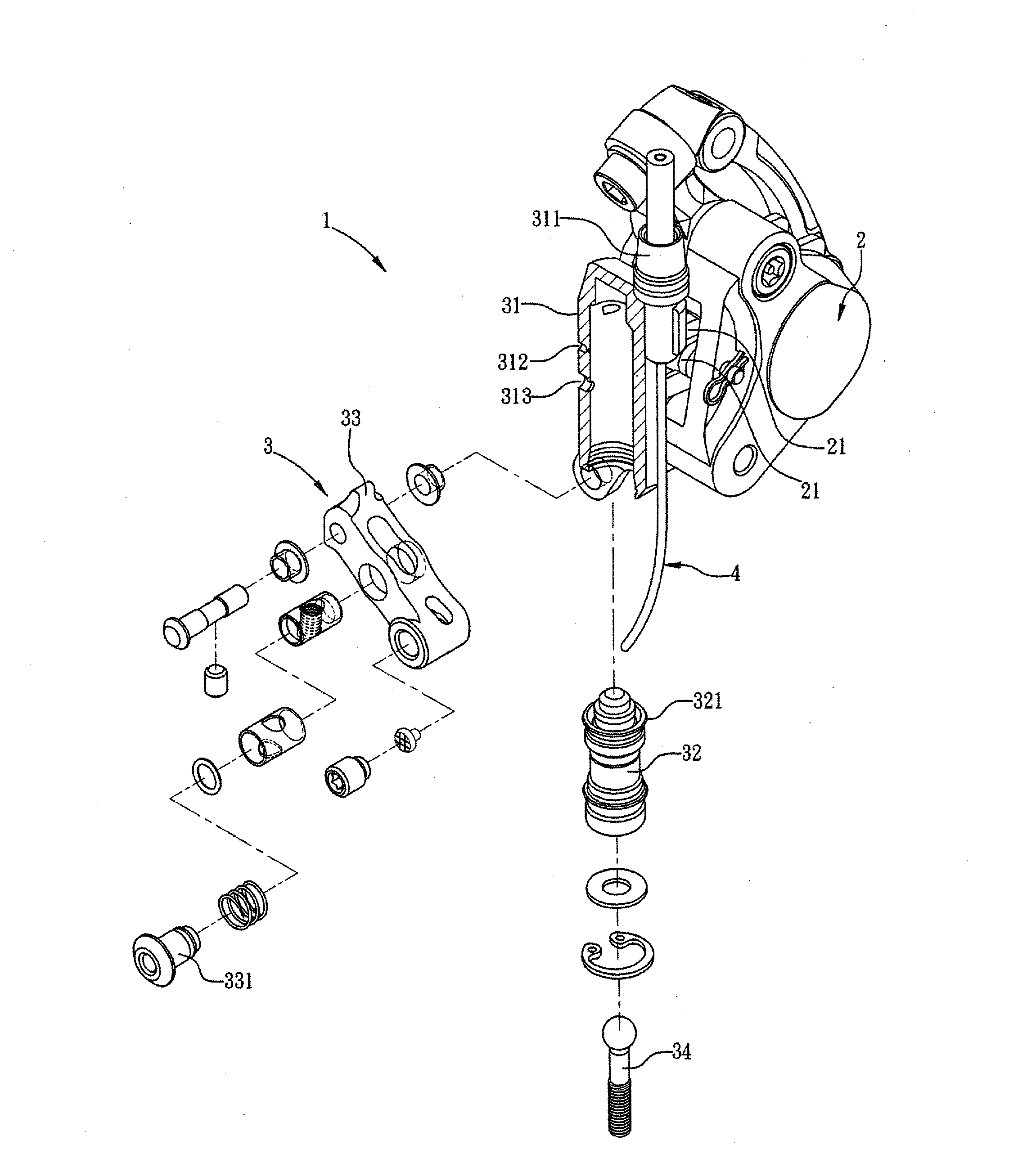
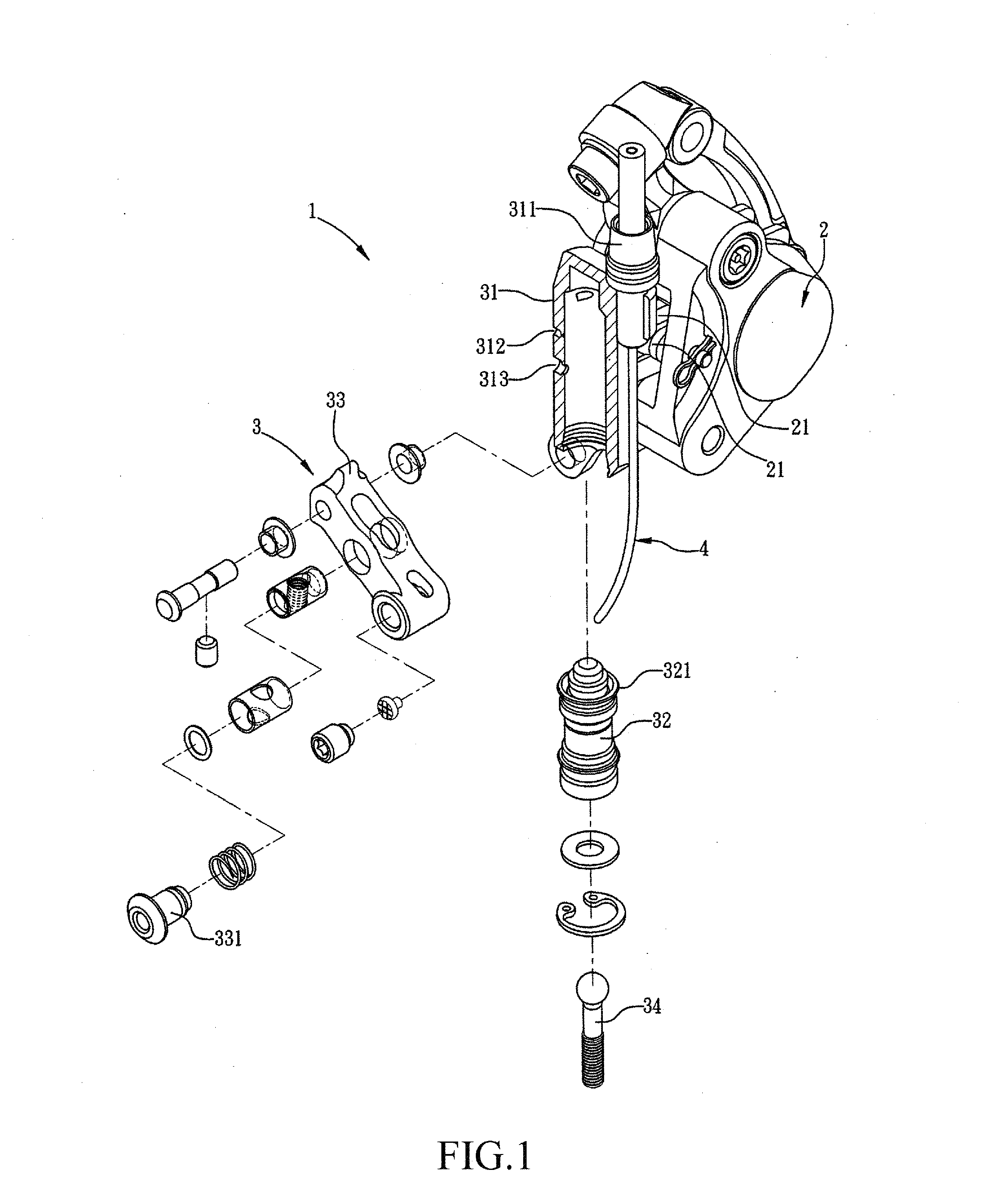
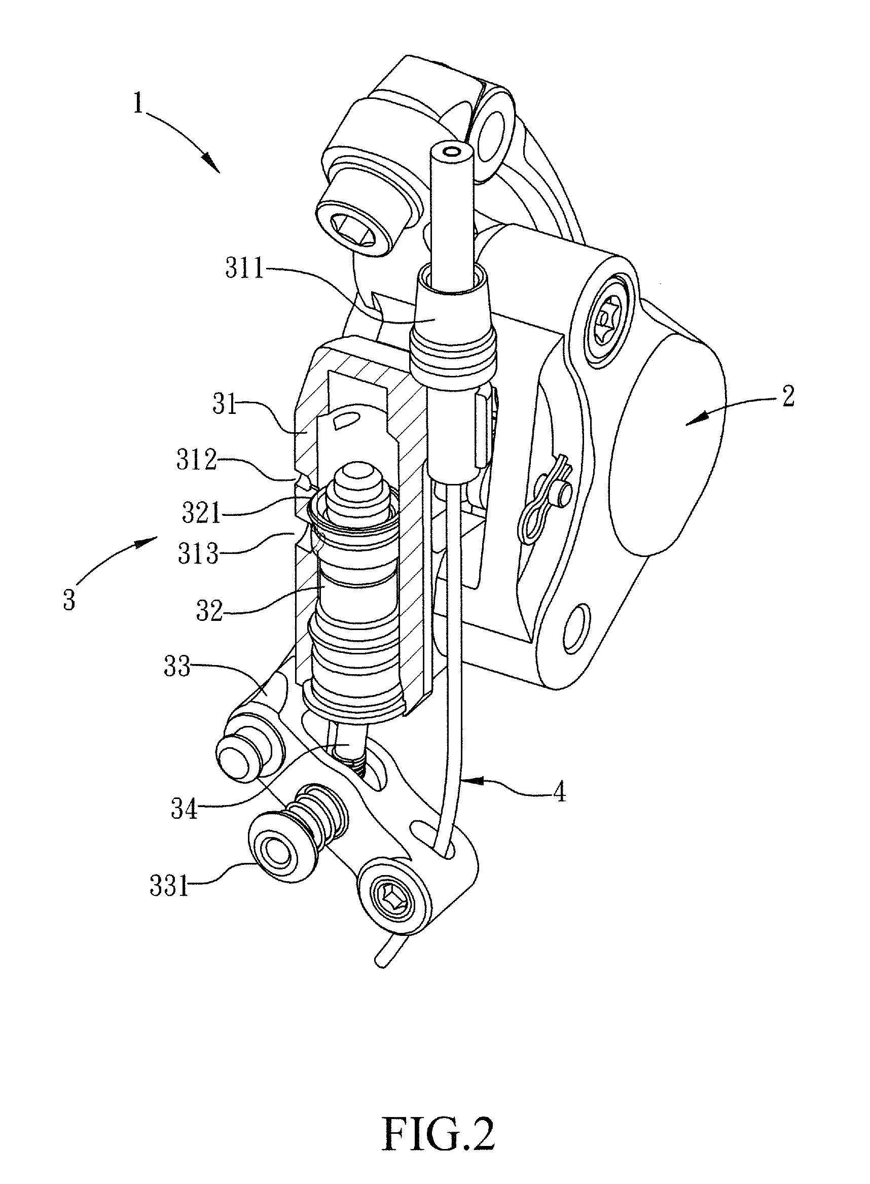
[0020]Referring to FIGS. 1-5, FIG. 1 is a partial exploded view of a control-by-wire hydraulic brake structure of bicycle according to the present invention; FIG. 2 is a partial cross-sectional view of the control-by-wire hydraulic brake structure of bicycle according to the present invention; FIG. 3 is a perspective view of the control-by-wire hydraulic brake structure of bicycle according to the present invention; FIG. 4 is also a perspective view of the control-by-wire hydraulic brake structure o...


PUM


Abstract

The present invention relates to a control-by-wire hydraulic brake structure of bicycle, which includes a caliper portion that is coupled to two brake shoes that are opposite to and spaced from each other; and a transmission portion, which has an end connected to the caliper portion to control the operation of the two brake shoes of the caliper portion and includes a fluid reservoir, a piston, and a transmission arm. The piston is movably received in the fluid reservoir. The transmission arm has an end pivotally connected to an end of the fluid reservoir that is distant from the caliper portion. The piston has an end that is connected to a predetermined location between two ends of the transmission arm. The transmission arm has an end that is distant from the pivotal connection with the fluid reservoir and is operatively coupled to a brake wire.

Description

TECHNICAL FIELD OF THE INVENTION[0001]The present invention generally relates to the field of bicycle brake, and more particularly to a control-by-wire hydraulic brake structure of bicycle.DESCRIPTION OF THE PRIOR ART[0002]Generally speaking, a structure that is adopted in a bicycle to achieve an effect of braking by hydraulic transmission can be classified as a control-by-wire hydraulic brake, where a brake grip is provided with a brake wire that is connected to a transmission component, and a fully hydraulic brake structure, where a transmission components are directly installed in the brake grip and the transmission components comprise at least a fluid reservoir, a piston, and connection rod (or a transmission arm), in which the transmission components are operatively coupled to the brake unit and the brake unit comprises at least one caliper (or clamping arm) and two brake shoes.[0003]The present invention is made to provide a control-by-wire hydraulic bicycle brake structure th...

Claims


Application Information

Patent Timeline
IPC IPC(8): B62L3/02B62L1/10
CPCB62L1/005
Inventor TSAI, SZU-FANG
Owner TEKTRO TECH
Why Eureka
Try Eureka