Circuit with an opto-electronic display unit

Inactive Publication Date: 2007-07-31
REIME GERD
View PDF20 Cites 35 Cited by
  • Summary
  • Abstract
  • Description
  • Claims
  • Application Information

AI Technical Summary

Benefits of technology

[0012]With the display unit formed by the light-emitting diodes receiving elements are associated in such a way that no separate mechanical keys are necessary. For operator control of such a regulating/adjusting unit, therefore, the display itself becomes the operator control element. There is therefore no need for either keys or cutouts for such keys. This, on the one hand, reduces the cost of manufacturing such an operator control unit and, on

Problems solved by technology

The drawback is, however, the need for mechanical cutouts in the operator control panel and the provision of appropriate keys.
The opto-receivers and opto-transmitters may be

Method used


Image

  • Circuit with an opto-electronic display unit
  • Circuit with an opto-electronic display unit
  • Circuit with an opto-electronic display unit

Examples


Example

[0036]The invention is described in detail below with reference to the accompanying drawings. However, the embodiments are merely examples, which do not restrict the inventive concept to a specific arrangement.

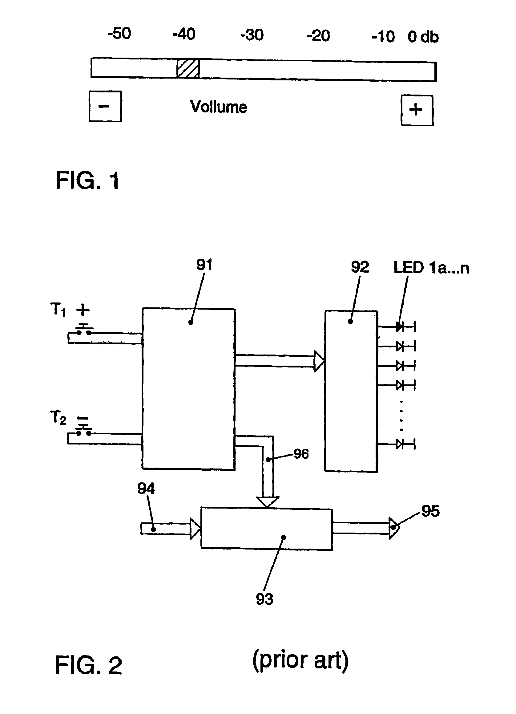
[0037]In the prior art, the switching assignment for an adjusting unit according to FIG. 1 comprises according to FIG. 2 a counting device 91, the instantaneous state of which is determined by the key functions T1 (e.g. +key) and T2 (e.g. −key). Each time the keys T1 and T2 are actuated, the counting device 91 counts one value increment upwards and / or downwards and passes this information on to the display driver 92, which allows the LED corresponding to the set value to emit light. Parallel thereto, the set value is passed on to the control apparatus and / or the value regulator 93. This value regulator 93 regulates e.g. the amplitude of an analogue audio signal 94 / 95 in accordance with the set value 96. Thus, always at least one external control signal T1 or T2 is required for...


PUM


Abstract

A circuit provided with an optoelectronic display unit. For discrete display of the settings of a regulating/control unit, said circuit comprises at least one detection element for detecting the actuation of an object in order to modify the settings of the regulating/control unit, whereby the detection element delivers an output signal corresponding to the desired modification. Several luminous diodes (1a, . . . , 1n), which are essentially arranged next to each other in a row and which emit luminous radiation, are used as display elements. A control device controls at least one of the luminous diodes (1a, . . . , 1n) according to the output signal in order to display the respective setting, in addition to the regulating/control unit for modification of the setting. In order to produce a quality display and operator unit, at least two receiver elements which are sensitive with respective to the luminous radiation of the luminous diodes (1a, . . . , 1n) are provided, acting as detection elements in order to detect the luminous radiation reflected by at least one luminous diode (1c) and by an object (2), and the control device controls at least one of the luminous diodes in addition to the regulating/control unit as a result of the output signal, which is formed according to the movement of the object relative to the luminous diode (1c) emitting luminous radiation, according to the movement of said object.

Description

REFERENCE TO RELATED APPLICATIONS[0001]The present application claims the priority of the German patent application 101 46 996.9, filed on Sep. 25, 2001, the disclosure content of which is hereby expressly also made the subject matter of the present application.FIELD OF THE INVENTION[0002]The invention relates to a circuit comprising an optoelectronic display unit.BACKGROUND OF THE INVENTION[0003]In the field of operator control elements, displays formed e.g. by a series of LEDs are known, which indicate a set value. This may be a row of LEDs, i.e. light-emitting diodes, which are arranged side by side and of which one element emits light and indicates an actual value. As a rule, the luminescent elements arranged in a row are suitably labelled to enable an association with a quantity such as e.g. a display in “dB” for volume control. Changeover to another value is effected mechanically e.g. by means of momentary-contact switches. Generally, to increase and reduce the value one mecha...

Claims


Application Information

Patent Timeline
IPC IPC(8): H01J40/14G01J1/32G09G5/00H05B37/02H03K17/94H03K17/945
CPCH03K17/943H03K17/9631G01S7/497G01S17/026G01S17/46H03K2217/94052H03K2217/94112G01S17/04
Inventor REIME, GERD
Owner REIME GERD
Why Eureka
Try Eureka