Light-emitting heat-dissipating device and packaging method thereof

Inactive Publication Date: 2008-01-31
DELTA ELECTRONICS INC
View PDF6 Cites 38 Cited by
  • Summary
  • Abstract
  • Description
  • Claims
  • Application Information

AI Technical Summary

Benefits of technology

[0015]As mentioned above, compared with the prior art, the light-emitting chip contacts the thermally conducting element in this invention. So, when the invention is used for a long time, the heat produced by one single light-emitting chip or plural light-emitting chips can be simultaneously, rapidly and uniformly transferred and dissipated in the same direction from the hot junction to the cold junction of the thermally conducting element through the thermally conducting element. This method can achieve the rapid heat dissipation in a short period of

Problems solved by technology

So, the heat dissipating efficiency influences the reliability and the lifetime of the electronic element.
Thus, the power of the LED package module is limited to about 0.1 watt.
However, when the LED package module 1 is used for a long time, the lead frame 13 cannot effectively dissipate the heat, and the accumulated heat influences

Method used


Image

  • Light-emitting heat-dissipating device and packaging method thereof
  • Light-emitting heat-dissipating device and packaging method thereof
  • Light-emitting heat-dissipating device and packaging method thereof

Examples


first embodiment

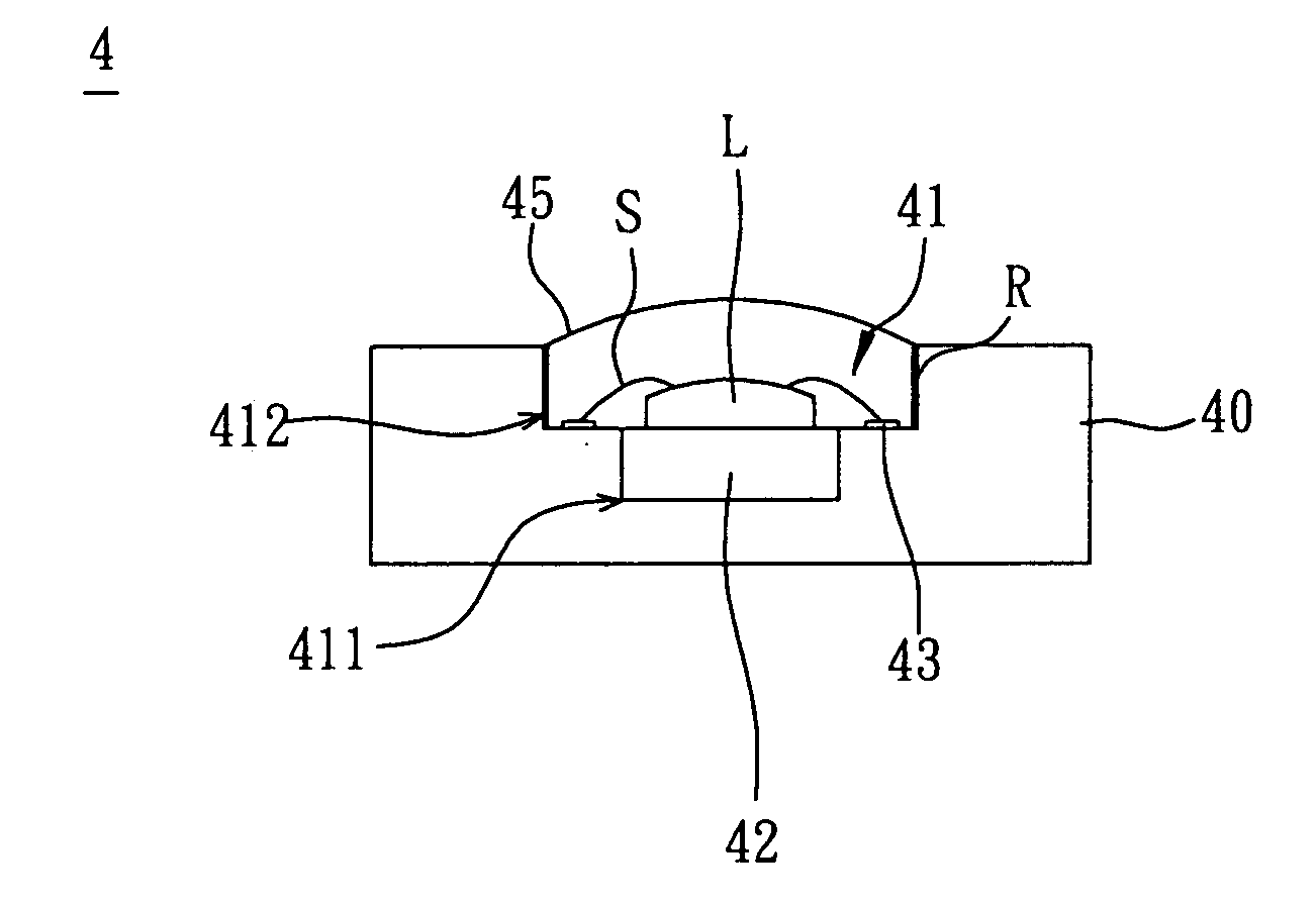
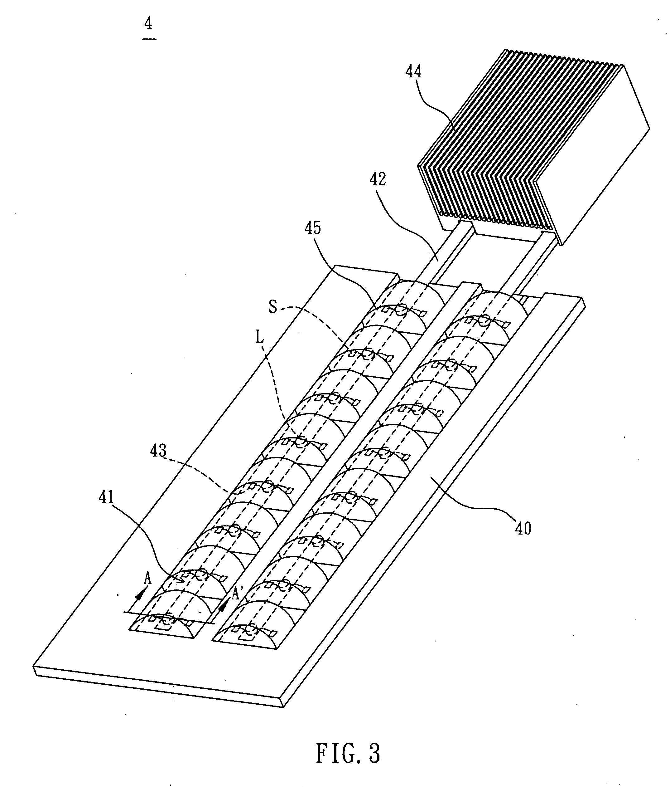
[0029]Referring to FIGS. 3 and 4, a light-emitting heat-dissipating device 4 according to the invention includes a circuit board 40 and at least one light-emitting chip L packaged on the circuit board 40. The circuit board 40 has at least one recess 41 and at least one thermally conducting element 42 disposed in the recess 41. The light-emitting chip L is disposed on the thermally conducting element 42. In this embodiment, the circuit board 40 has a plurality of thermally conducting elements 42, and a plurality of light-emitting chips L is disposed on each thermally conducting element 42.

[0030]The circuit board 40 is not particularly restricted and may be a printed circuit board (PCB) or a low-temperature co-fired ceramic (LTCC) circuit board, which is typically used. A plurality of contact pads 43 is exposed from a surface of the circuit board 40 and serves as connections between the light-emitting chip L and a circuit layout of the circuit board 40. The light-emitting chip L is a ...

second embodiment

[0038]Referring to FIGS. 10 and 11, a light-emitting heat-dissipating device 5 according to the invention includes at least one light-emitting chip L, a circuit board 51 and a carrier 52.

[0039]The circuit board 51 has a slot 511 and one surface of the carrier 52 has at least one recess 521 and at least one thermally conducting element 53 disposed in the recess 521. In this embodiment, the carrier 52 has a recess 521 and a thermally conducting element 53. The circuit board 51 is disposed on the carrier 52, and the slot 511 is correspondingly disposed on the recess 521 so that the thermally conducting element 53 is also disposed in the slot 511, and the light-emitting chip L is disposed on the thermally conducting element 53 and packaged on the circuit board 51.

[0040]The structures, features and effects of the light-emitting chip L and the thermally conducting element 53 of this embodiment are the same as those of the light-emitting chip L and the thermally conducting element 42 of th...


PUM


Abstract

A light-emitting heat-dissipating device includes at least one light-emitting chip and a circuit board. The circuit board has at least one recess and at least one thermally conducting element disposed in the recess. The light-emitting chip is disposed on the thermally conducting element and connected to the circuit board via contact pads electrically connected to a circuit layout of the circuit board. In addition, the light-emitting chip is package by a filler on the circuit board. A packaging method of the light-emitting heat-dissipating device is also disclosed.

Description

CROSS REFERENCE TO RELATED APPLICATIONS[0001]This Non-provisional application claims priority under 35 U.S.C. §119(a) on Patent Application No(s). 095127657 filed in Taiwan, Republic of China on Jul. 28, 2006, the entire contents of which are hereby incorporated by reference.BACKGROUND OF THE INVENTION[0002]1. Field of Invention[0003]The invention relates to a light-emitting heat-dissipating device and a packaging method thereof, and, in particular, to a light-emitting heat-dissipating device for dissipating heat using a heat pipe, and a packaging method thereof.[0004]2. Related Art[0005]Due to the progress of the technology, various electronic products need to have more and more functions. In addition to the continuous upgrade of the speed of the desktop computer, portable mobile electronic devices, such as personalized products including a notebook computer, a mobile phone, a mini CD and a hand-held computer, have become the important trend of the development. However, as the prod...

Claims


Application Information

Patent Timeline
IPC IPC(8): H01L33/00H01L21/00H01L33/64
CPCF21K9/00F21V29/763H01L33/648H05K1/0203H05K3/107H05K2201/0919H05K2201/1028H01L2224/48091H01L2224/48247H01L25/0753F21V29/677F21V29/006H01L2924/00014H01L2924/00H01L2924/12044F21V29/87F21V29/51F21V29/503
Inventor LEE, YI-SHENGYU, CHIH-HAOCHENG, CHIN-MINGHSIEH, YU-PINGCHANG, YU-CHINGHUANG, YI-HONG
Owner DELTA ELECTRONICS INC
Why Eureka
Try Eureka