Drip resistant dispensing valve for fluids

Inactive Publication Date: 2007-08-09
INT DISPENSING CO
View PDF37 Cites 37 Cited by
  • Summary
  • Abstract
  • Description
  • Claims
  • Application Information

AI Technical Summary

Benefits of technology

[0023]Such valve is also preferably configured so as to withstand sterilization procedures including irradiation up to 5.0 MRAD and high temperature steam and chemical sterilization processes without degradation of the integrity of the valve structure or operation, and thus may be used for dispensing a wide variety of products ranging from aseptic products (free from microorganisms) to non-sterile products.
[0024]The simplicity and functionality of the drip resistant dispensing valve of the instant invention enables its manufacture and automatic

Problems solved by technology

Unfortunately, many of the dispensing valve mechanisms available fail to provide a dispensing outlet that does not avoid the collection of liquid on its surfaces, thereby resulting in the unwanted release of liquid from the dispensing outlet after it has been shut off.
Thus, not all of the liquid is caught in the receptacle; rather, some accumulates on such inner surfaces and may drip off such surfaces after the dispensing operation.
Still further, many of the currently employed dispensing valves promote the development of unsanitary conditions in and around the dispensing outlet.
Many such pathogens and the like may not be readily ascertainable through visual inspection and may survive cleaning of the dispensing outlet.
This may lead to such unwanted organisms traveling further into the dispensing valve, and likewise into a container to which the dispensing valve is attached and contaminating the liquid within.
Another valve, shown in U.S. Pat. No. 3,263,875 to Lofdahl, has a similarly configured dispensing outlet and a push-button actuator, and once again lacks any provision to prevent residual undispensed fluid from collecting in and/or dripping from the discharge outlet, and fully exposes the discharge outlet to the outside environment, thus promoting contact with potentially contaminated surfaces.
Likewise, commercial attempts have been made to provide low-cost dispensing valves for use with disposable containers, but such efforts have met with limited success.
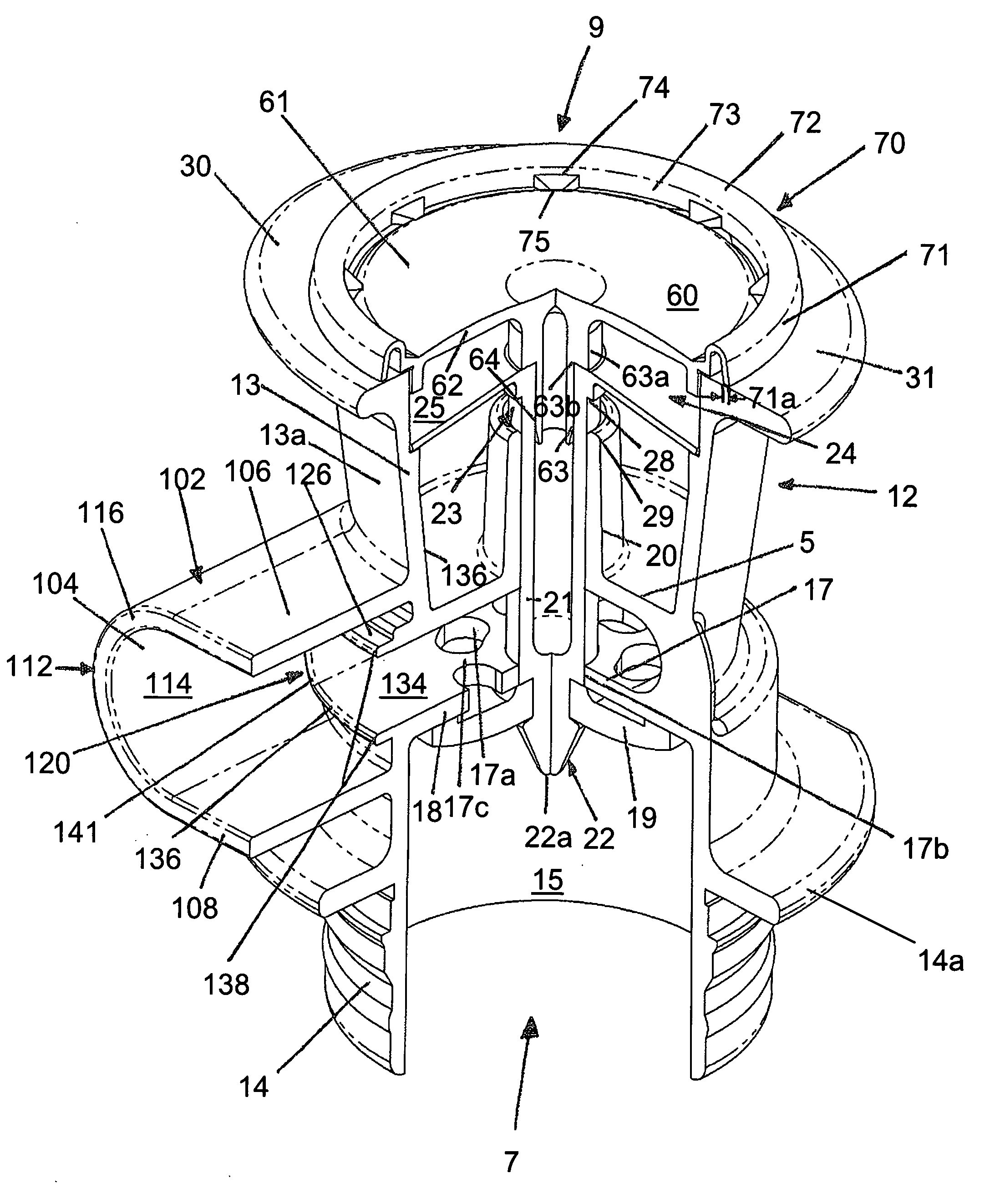
Moreover, such valve

Method used


Image

  • Drip resistant dispensing valve for fluids
  • Drip resistant dispensing valve for fluids
  • Drip resistant dispensing valve for fluids

Examples


Embodiment Construction

[0037]The invention summarized above and defined by the enumerated claims may be understood by referring to the following description, which should be read in conjunction with the accompanying drawings in which like reference numbers are used for like parts. This description of an embodiment, set out below to enable one to build and use an implementation of the invention, is not intended to limit the enumerated claims, but to serve as a particular example thereof. Those skilled in the art should appreciate that they may readily use the conception and specific embodiments disclosed as a basis for modifying or designing other methods and systems for carrying out the same purposes of the present invention. Those skilled in the art should also realize that such equivalent assemblies do not depart from the spirit and scope of the invention in its broadest form.

[0038]Referring to the drawings, FIG. 1 shows a drip resistant dispensing valve 12 in accordance with one embodiment of the prese...


PUM

PropertyMeasurementUnit
Thicknessaaaaaaaaaa
Forceaaaaaaaaaa
Radiusaaaaaaaaaa

Abstract

A drip resistant dispensing valve for fluids is disclosed, which provides a dispensing outlet configured to minimize the tendency for fluid to drip from the valve following a dispensing operation. The dispensing outlet exhibits curved interior surfaces and a curved outlet face construction; the face situated a distance away from the valve body. Such construction assists in minimizing the retention of fluid on the surfaces of the dispensing outlet, and migration of the fluid to surfaces outside of the dispensing outlet that could tend to promote growth of biological contaminates and/or provide additional surfaces that could pool fluid following a dispensing operation and thereafter drip from the valve. A shell is provided around the dispensing outlet to assist in avoiding contamination of the valve and of the fluid being dispensed through the valve, and to aid in positioning a receptacle for receiving fluid from the dispensing valve.

Description

CROSS REFERENCE TO RELATED APPLICATION[0001]This application is based upon and claims benefit of copending and co-owned U.S. Provisional Patent Application Ser. No. 60 / 771,321 entitled “Drip Resistant Dispensing Valve for Fluids”, filed with the U.S. Patent and Trademark Office on Feb. 8, 2006, the specification of which is incorporated herein by reference.BACKGROUND OF THE INVENTION[0002]1. Field of the Invention[0003]The present invention relates to fluid dispensing apparatus and, more particularly, to a robust, relatively simple, low-cost, and easily actuatable dispensing valve for dispensing fluid from a source of such fluid, which valve is configured so as to reduce the tendency for residual fluid to collect on and ultimately drip from the valve following a dispensing operation, and to minimize the risk of contamination of the valve and the fluid that is to be dispensed.[0004]2. Description of the Background[0005]Dispensing valves for dispensing fluid from fluid containers, sys...

Claims


Application Information

Patent Timeline
IPC IPC(8): B67D3/00F16K31/00
CPCF16K23/00B65D47/248B67D3/00F16K21/00
Inventor ALLANSON, GARY R.FRIEDMAN, MITCHELL A.
Owner INT DISPENSING CO
Why Eureka
Try Eureka