Transflective liquid crystal display

Inactive Publication Date: 2007-10-18
INNOLUX CORP +1
View PDF9 Cites 35 Cited by
  • Summary
  • Abstract
  • Description
  • Claims
  • Application Information

AI Technical Summary

Benefits of technology

[0026] A sixth objective of this invention is to provide apparatus, methods, system and devices for reducing the manufacturing cost of transflective LCD by eliminating complicated fabrication processes such as double cell gap, double domain alignment, and patterned retardation film.
[0027] A seventh objective of the present inventio

Problems solved by technology

However, under the dark ambient, the reflective LCD cannot show the image well.
However, to control the uniformity of the metallic film thickness over a large area is not easy.
The transflective LCD based on discontinuous reflective film also has some problems, including different electro-optic properties and unequal color reproduction between transmissive and reflective modes.
However, it increases the complexity of the device fabrication process.
However, to fabricate different cell gaps for transmissive and reflective parts, which is also called double cell-gap approach, is not easy.
Even though this approach reduces the fabrication difficulty of the double cell gap structure; however, the

Method used


Image

  • Transflective liquid crystal display
  • Transflective liquid crystal display
  • Transflective liquid crystal display

Examples


first embodiment

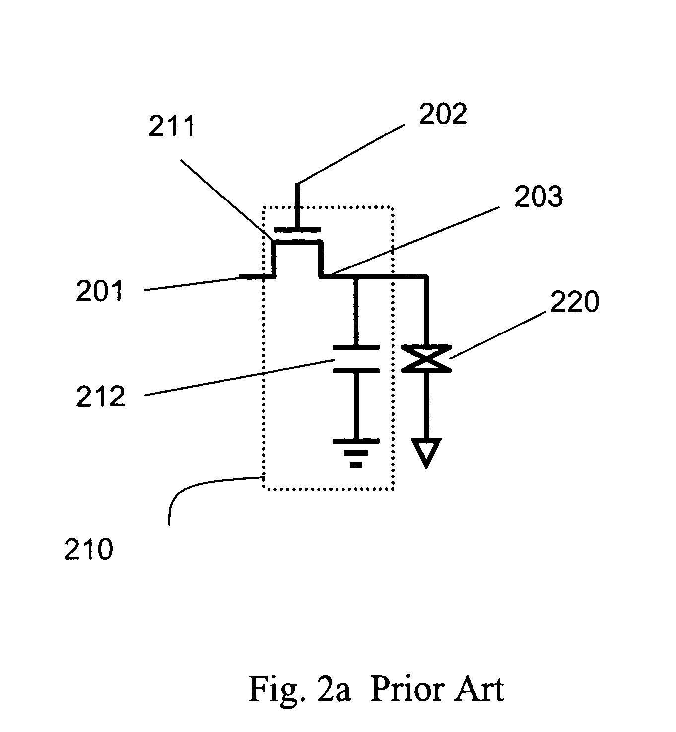
[0057] In an embodiment of the present invention, each of those sub-pixels 901, 902, 903, and 904 is driven by an independent electronic switch comprising at least one thin film transistor and at least one capacitor. FIG. 10a shows the location of sub-pixel electronic circuits in the present invention according to the As shown, the first reflective sub-pixel 901 has an electronic circuit 1011, the second reflective sub-pixel 902 is driven by with electronic circuit 1012, the third reflective sub-pixel 903 is driven by electronic circuit 1013, and the transmissive sub-pixel 904 is driven by electronic circuit 1014 as well.

[0058] Each sub-pixel's electronic circuit is within the region of the corresponding sub-pixel. In the three reflective sub-pixels, each sub-pixel has an opaque reflective mirror and the electronic circuits are located under the reflective mirror. As a result, the electronic circuits themselves do not affect the aperture ratio of the reflective sub-pixel, yielding ...

second embodiment

[0059]FIG. 10B shows the location of sub-pixel electronic circuits in the present invention. To increase the aperture ratio of the transmissive sub-pixel 904, the sub-pixel electronic circuits 1022 is also located under the reflectors of the reflective sub-pixels 901, 902, and 903. In this embodiment, the aperture ratio of all sub-pixels is maximized. Unlike the prior art transflective LCD's pixel structure shown in FIG. 1, the pixel structure of the present invention shown in FIG. 10b increases the size of all sub-pixels.

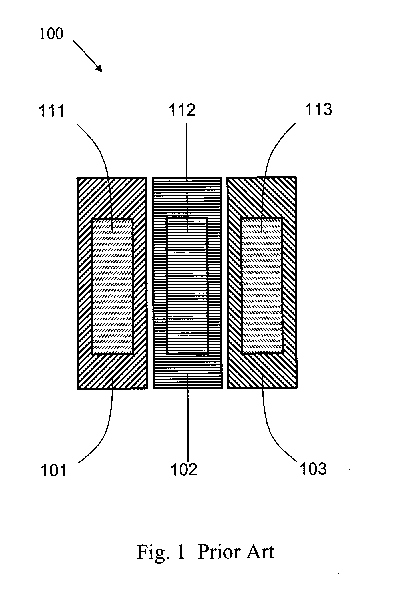
[0060] In the prior art transflective LCD, each pixel is divided into three different primary color sub-pixels. And the size of each sub-pixel equals to each other. Each sub-pixel has a discontinuous reflector film so that some part of the sub-pixel is transparent and the other part of the sub-pixel is opaque. The transparent part allows the backlight pass through it while the opaque part serves as the reflector to reflect the incident ambient light back to the vie...

third embodiment

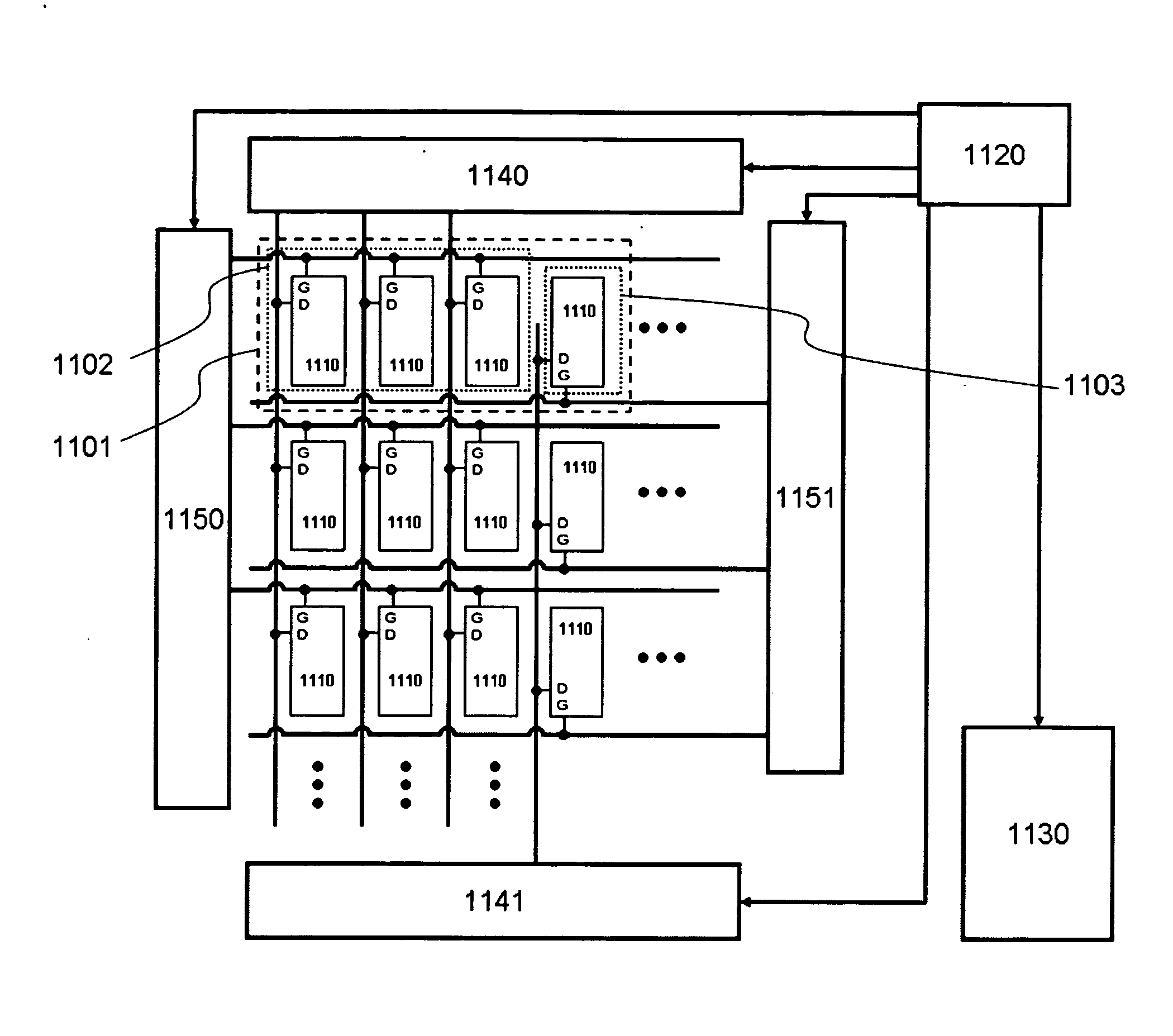
[0062]FIG. 11 shows the present invention based on the pixel structure shown in FIG. 9. In the figure, one pixel 1101 has three reflective sub-pixels 1102 and one transmissive sub-pixel 1103. The reflective sub-pixels 1102 are driven by the scan driver 1150 and the data driver 1140, while the transmissive sub-pixels 1103 is driven by the scan drivers 1151 and the data drivers 1141. In an embodiment of the present invention, both reflective sub-pixels 1102 and transmissive sub-pixels 1103 are driven by a single-switch based electronic circuit 1110. The video data is converted by a timing control unit 1120 and is distributed to the data drivers 1140 and 1141 and scan drivers 1150 and 1151 for the reflective and transmissive sub-pixels, respectively. The timing control unit 1120 also controls the backlight 1130 to synchronize the display of the reflective and transmissive color images.

[0063]FIG. 12 shows an example of the operation timing diagram of the transflective LCD shown in FIG. ...


PUM


Abstract

The apparatus, methods, system and devices of the present invention provides transflective LCD system structure wherein each pixel is composed of at least three reflective sub-pixels and at least one transmissive sub-pixel. The reflective sub-pixels have a color filter layer for displaying color reflective images and the transmissive sub-pixel it is driven by color sequential imaging method for displaying a color transmissive image. The configuration of the sub-pixels and the location of the sub-pixel electronics increases the aperture ratio of both transmissive sub-pixel and reflective sub-pixel to improve the image brightness and lower the overall power consumption of the device.

Description

FIELD OF THE INVENTION [0001] This invention relates to transflective liquid crystal displays and, in particular, to apparatus, methods, system and devices for a transflective liquid crystal display having a pixel structure including at least three reflective sub-pixels and one transmissive sub-pixel which improves the aperture sizes of both reflective and transmissive sub-pixels to provide brighter image for both reflective and transmissive modes. BACKGROUND AND PRIOR ART [0002] Since liquid crystal display (LCD) was discovered, two types of the LCD have been developed and widely used in information display tools, including cell phones, laptops and desktop computers, televisions, and so on. One type is the transmissive LCD which employs a light source called “backlight” at the back side of the liquid crystal cell. The other type is the reflective LCD which uses ambient light as a light source instead of backlight to display an image. Because of using ambient light, the reflective L...

Claims


Application Information

Patent Timeline
IPC IPC(8): G09G3/36
CPCG02F1/133514G02F1/133555G02F1/1368G02F2001/133622G09G3/3607G09G2310/02G09G3/3659G09G2300/0426G09G2300/0456G09G2300/0809G09G2300/0842G09G3/3648G02F1/133622
Inventor LEE, JU-HYUNZHU, XINYUWU, SHIN-TSON
Owner INNOLUX CORP
Why Eureka
Try Eureka