Swivel mounted antenna

Active Publication Date: 2015-09-10
THE UNITED STATES OF AMERICA AS REPRESENTED BY THE SECRETARY OF THE NAVY
View PDF17 Cites 0 Cited by
  • Summary
  • Abstract
  • Description
  • Claims
  • Application Information

AI Technical Summary

Benefits of technology

[0005]The combination of a ground supported tripod and a vehicle supported swivel mount apparatus would enable a SATCOM antenna to be used in a dual use capacity. The antenna could be mounted on a tripod that is stationary on the ground, and also could be quickly connected to or disconnected from the tripod depending on the operational need for the antenna. The dual use functionality would allow the antenna to be used while either attached to a tripod, or for mobile use while installed or mounted on a vehicle via a swivel mount apparatus.
[0006]Current mounting devices do not allow antennas to be easily in

Problems solved by technology

Current mounting devices do not allow antennas to be easily installed on, or removed from a vehicle, while permitting operators

Method used


Image

  • Swivel mounted antenna
  • Swivel mounted antenna
  • Swivel mounted antenna

Examples


Example

DETAILED DESCRIPTION OF THE DRAWINGS

[0022]The embodiments of the invention described herein are not intended to be exhaustive or to limit the invention to precise forms disclosed. Rather, the embodiments selected for description have been chosen to enable one skilled in the art to practice the invention.

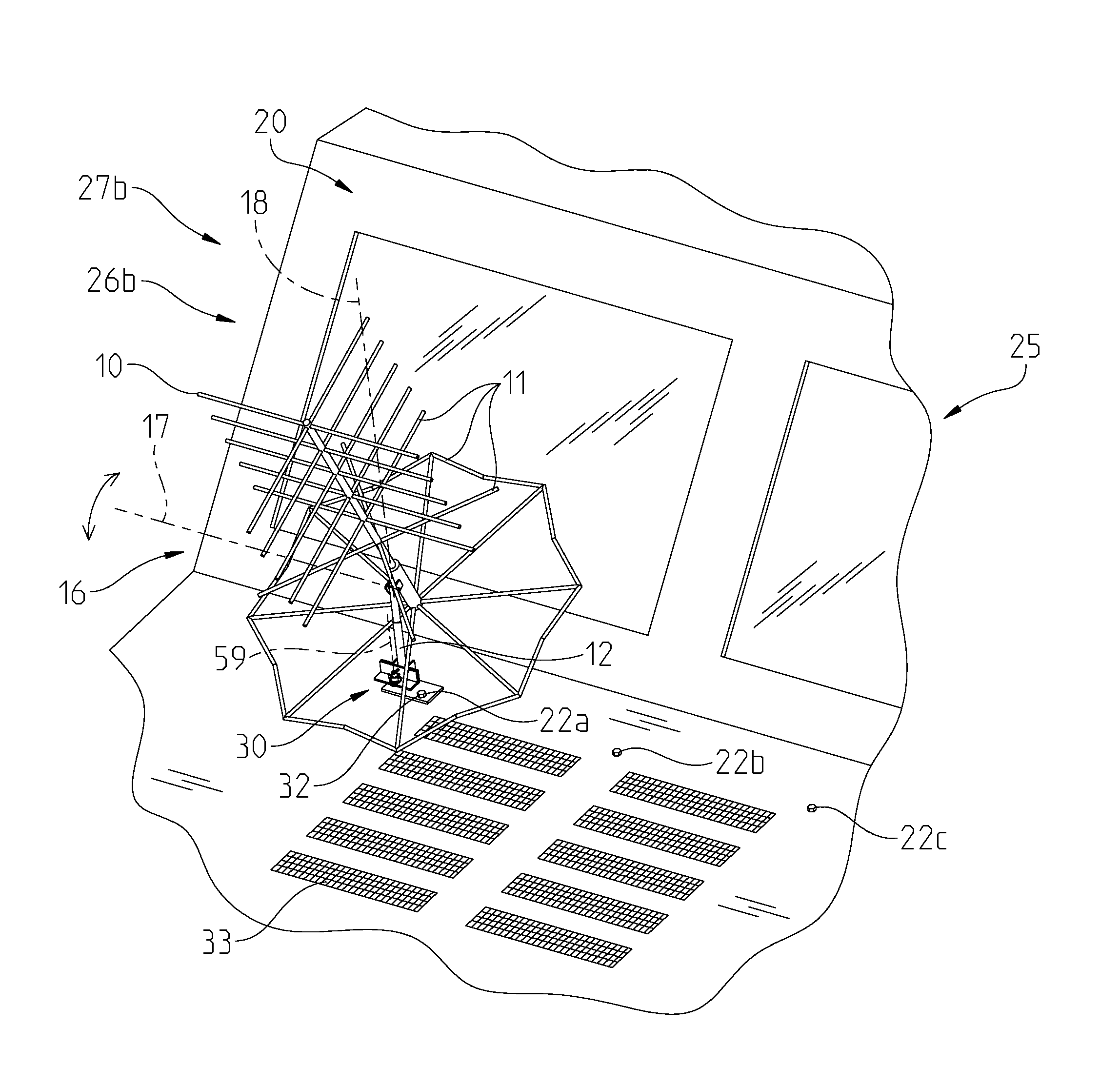
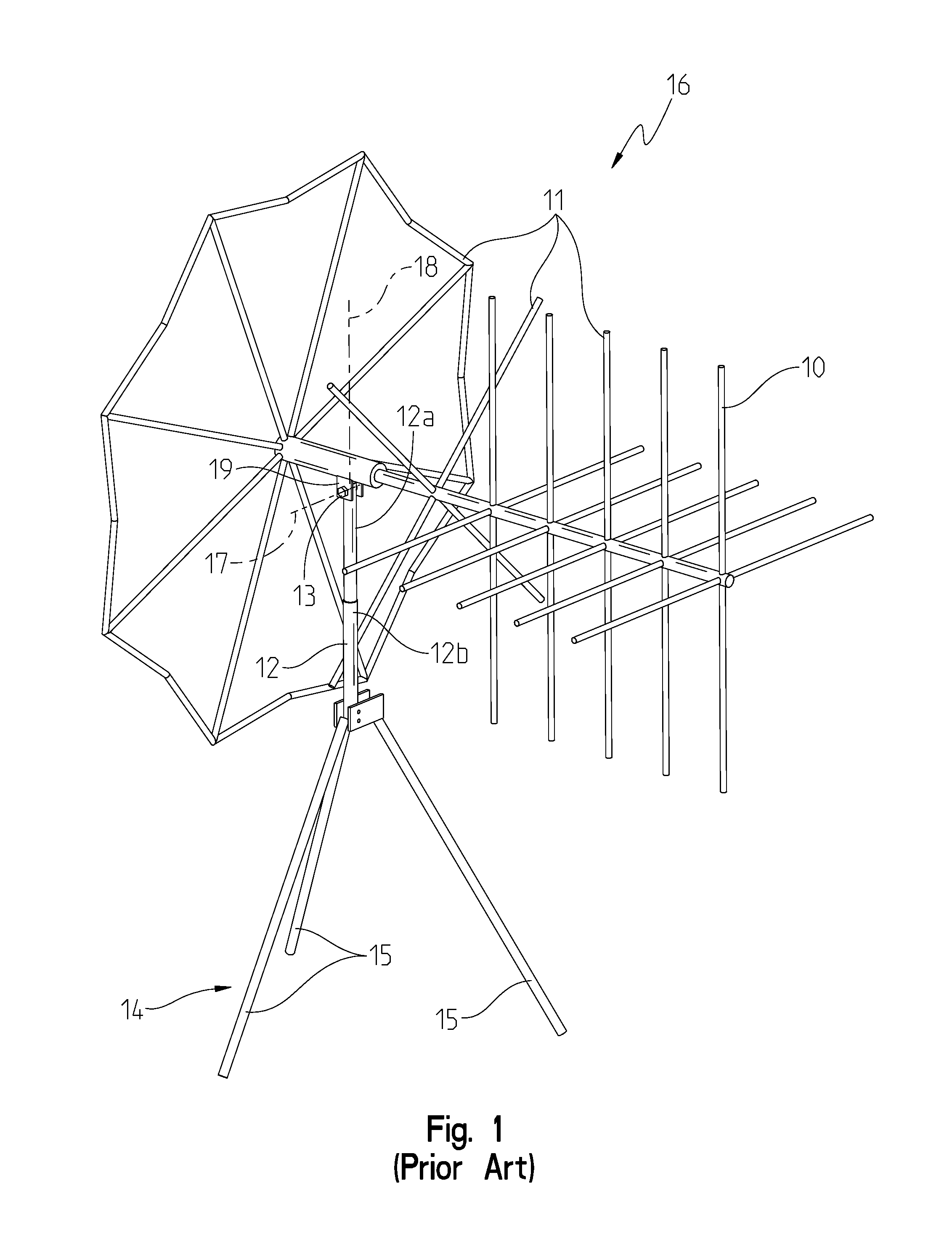
[0023]FIG. 1 shows a prior art equipment item and, more particularly, a SATCOM antenna system 16 including an antenna 10 mounted on a tripod 14. It is known that the tripod 14 includes legs 15 that may be used to stabilize the antenna 10 on the ground, including uneven terrain. Antenna system 16 generally includes antenna post 12 mechanically coupled to antenna 10 and a pivot pin 13 defining a conventional elevational pivot point or axis 17.

[0024]Antenna 10 illustratively may be of conventional design as including two sections with several antenna elements or blades 11 configured to receive and / or transmit electromagnetic signals within a predetermined frequency range. More particula...


PUM

PropertyMeasurementUnit
Fractionaaaaaaaaaa
Angleaaaaaaaaaa
Angleaaaaaaaaaa

Abstract

A swivel mount apparatus and method for installing a swivel mount apparatus on a vehicle. The swivel mount apparatus includes a first member, a second member rotatably coupled to the first member, and a mounting post affixed to the first member and extending upwardly relative to the first member, wherein the mounting post receives the second member. A receiving space is defined by the second member and receives an accessory, such that the accessory may be adjusted relative to the vehicle.

Description

CROSS-REFERENCE TO RELATED APPLICATION[0001]This application claims priority to U.S. Provisional Application Ser. No. 61 / 947,768, filed on Mar. 4, 2014, the disclosure of which is expressly incorporated herein by reference.STATEMENT REGARDING FEDERALLY SPONSORED RESEARCH OR DEVELOPMENT[0002]The invention described herein was made in the performance of official duties by an employee of the Department of the Navy and may be manufactured, used and licensed by or for the United States Government for any governmental purpose without payment of any royalties thereon. This invention (NC 103,080) is assigned to the United Stated Government and is available for licensing for commercial purposes. Licensing and technical inquiries may be directed to the Technology Transfer Office, Naval Surface Warfare Center Crane, email: Cran_CTO@navy.mil.BACKGROUND AND SUMMARY OF THE DISCLOSURE[0003]The present invention relates to a swivel mounted (i.e., rotatable) antenna system that can be mounted on any...

Claims


Application Information

Patent Timeline
IPC IPC(8): H01Q3/08H01Q1/32
CPCH01Q1/3275H01Q3/08H01Q1/12H01Q19/30Y10T29/49826
Inventor KNIGHT, BARRY W.
Owner THE UNITED STATES OF AMERICA AS REPRESENTED BY THE SECRETARY OF THE NAVY
Why Eureka
Try Eureka