
Shading device and method for installing the casing of said shading device

Inactive Publication Date: 2012-08-16
GAVIOTA SIMBAC
View PDF9 Cites 0 Cited by
  • Summary
  • Abstract
  • Description
  • Claims
  • Application Information

AI Technical Summary

Benefits of technology

[0001]The present invention relates to a shading device which runs along guide rails allowing said device to be installed and removed easily regardless of the area in which said device is arranged.
[0002]The shading device prevents wear of the canvas due to the arrangement thereof relative to the guide rails along which said canvas slides.
[0003]Likewise, the shading device allows the canvas-winding casing to be placed in an intermediate position relative to the guide rails, enabling the configuration of shading devices in which some rails are longer than others.

Problems solved by technology

This involves a large amount of work, and even more when the guide rails are of great length and are arranged on a glass surface.
Likewise, when the casing of the previous shading device must be assembled forming an angle with the wall against which it is normally assembled or the latter is stepped, the guide rails only reach the casing, there being a gap between the mentioned casing and the wall, therefore it is not possible to fix said guide rails to that wall.
In addition, in the previous device there is the risk of friction between the canvas and the guide rails due to the fact that the position of the casing makes the canvas slide very close to said guide rails, with the consequent deterioration thereof.

Method used


Image

  • Shading device and method for installing the casing of said shading device
  • Shading device and method for installing the casing of said shading device
  • Shading device and method for installing the casing of said shading device

Examples


first embodiment

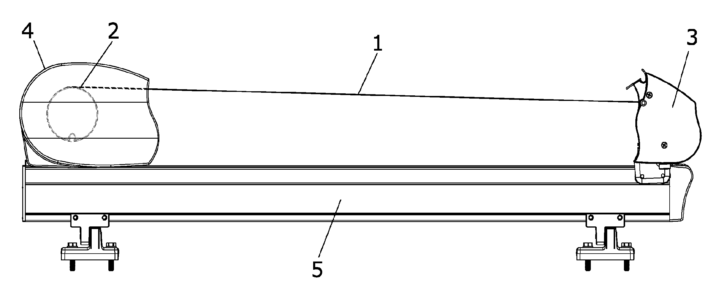
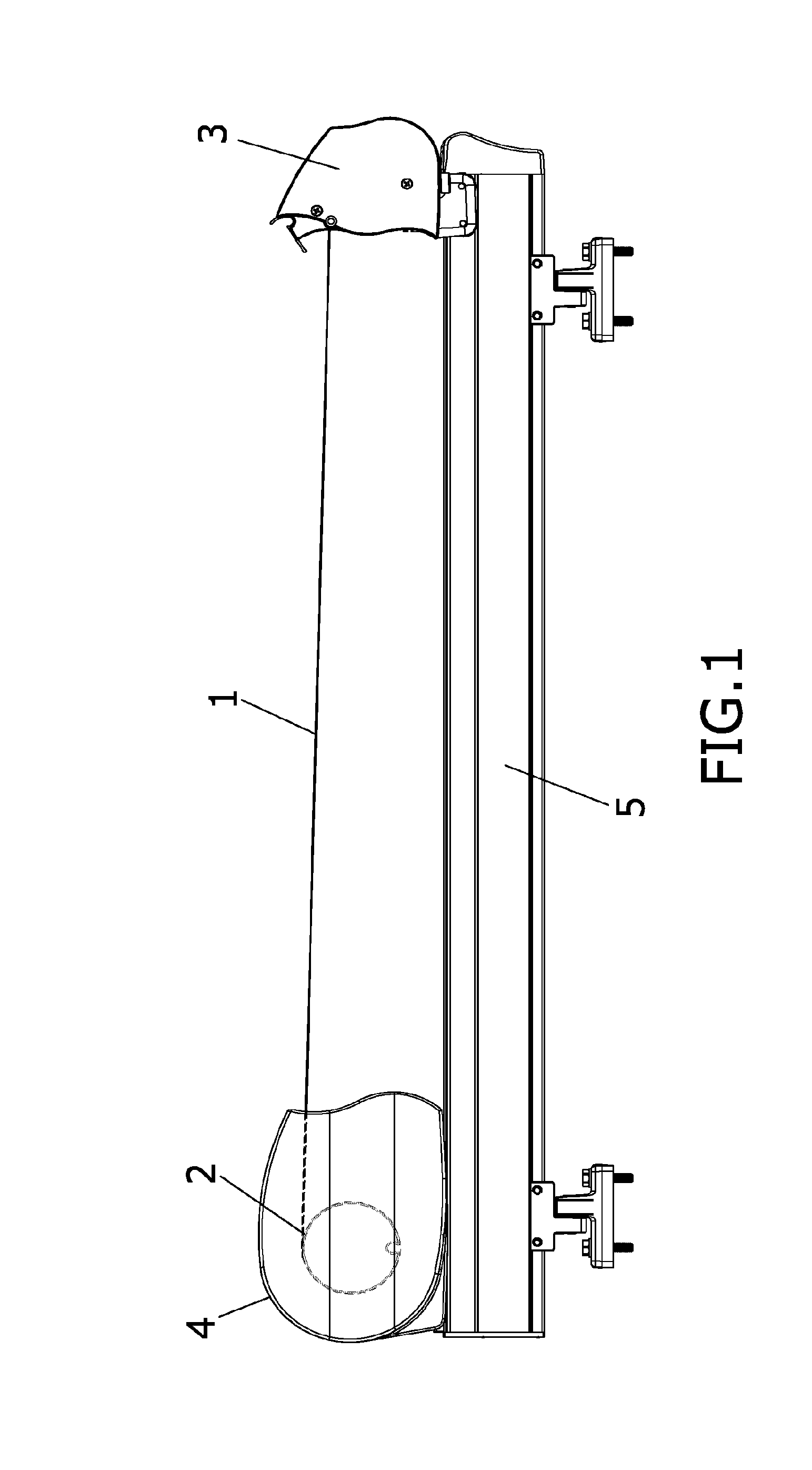
[0037]In a first embodiment, these guide rails (5) have a profile with a T-shaped gap in the upper face thereof, as shown in FIG. 1, for housing the head of a screw (6) and subsequently carrying out the fixing to the guide rails (5) of fixing means (7) for fixing the casing (4).

second embodiment

[0038]In a second embodiment, not shown in the figures, the guide rails (5) have a cross-shaped profile for leaving a gap for the part of the screw projecting from the nut.

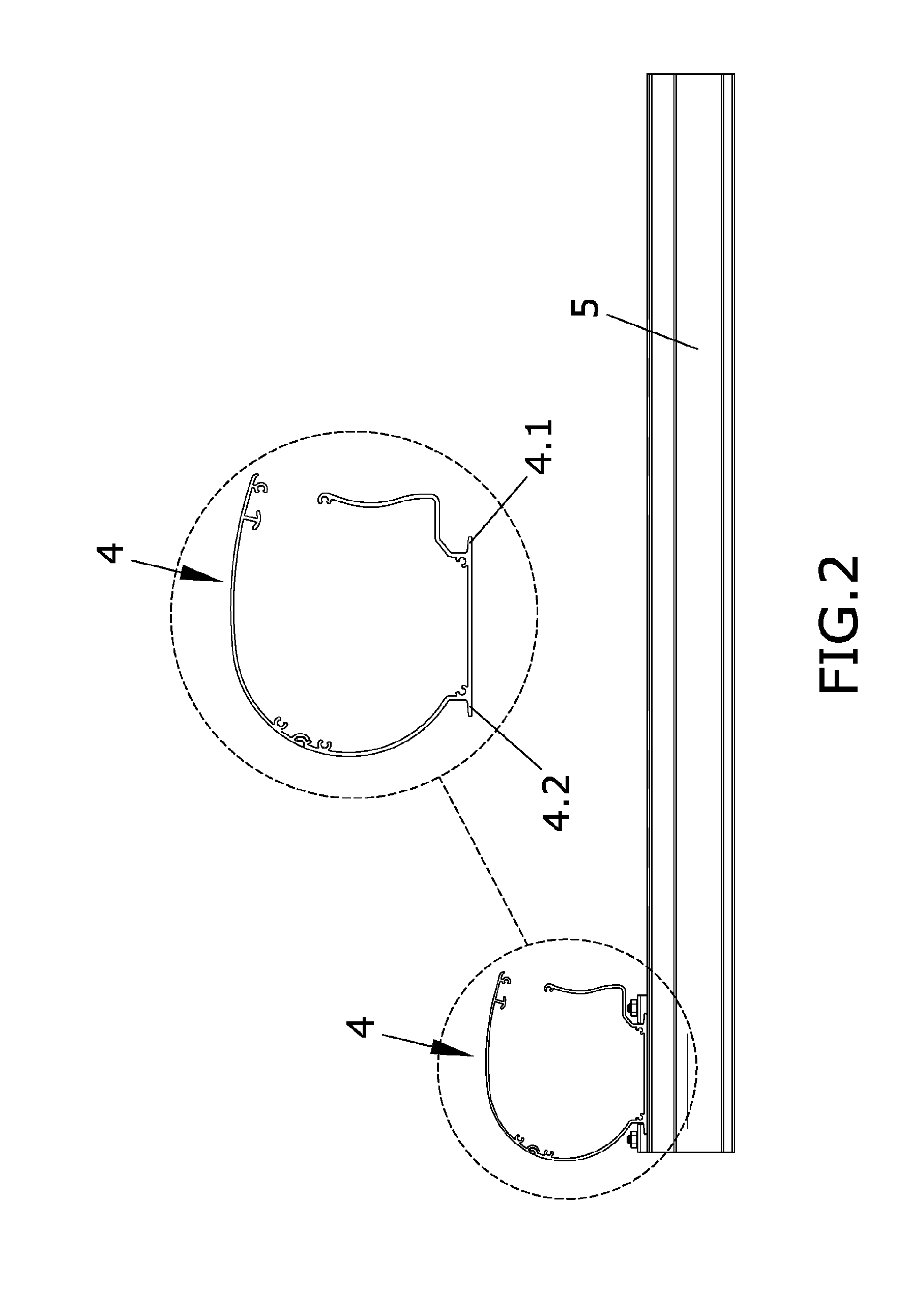
[0039]The casing (4) is arranged on top of the guide rails (5) and is fixed to such guide rails (5) by the mentioned fixing means (7) which comprise two grips, a front grip (7.1) and a rear grip (7.2) which have a housing (7.1.1, 7.2.1) to house front (4.1) and rear (4.2) antagonist flanges of the casing (4).

[0040]The grips (7.1, 7.2) are fixed to the guide rails (5) by means of the screw (6) housed in said guide rails (5) which traverses a hole (7.1.2, 7.2.2) present in each grip (7.1, 7.2) and is fixed by means of a nut (8).

[0041]The front grip (7.1) has a lower projection (7.1.3) fitting in a groove (5.1) present at the upper part of the guide rails (5) to prevent the rotation of said front grip (7.1) when the screw (6) is screwed to the nut (8), this protrusion not being necessary in the rear grip (7.2) to fac...


PUM


Abstract

The present invention relates to a shading device which runs along guide rails, allowing said device to be installed and removed easily regardless of the area in which said device is arranged. The shading device prevents wear of the canvas due to the arrangement thereof relative to the guide rails along which said canvas slides. Likewise, the shading device allows the canvas-winding casing to be placed in an intermediate position relative to the guide rails, enabling the configuration of shading devices in which some rails are longer than others.

Description

OBJECT OF THE INVENTION[0001]The present invention relates to a shading device which runs along guide rails allowing said device to be installed and removed easily regardless of the area in which said device is arranged.[0002]The shading device prevents wear of the canvas due to the arrangement thereof relative to the guide rails along which said canvas slides.[0003]Likewise, the shading device allows the canvas-winding casing to be placed in an intermediate position relative to the guide rails, enabling the configuration of shading devices in which some rails are longer than others.BACKGROUND OF THE INVENTION[0004]Shading devices by means of a canvas which can be wound on a shaft and opened by extending a load bar attached to the canvas are known in the state of the art, the canvas shaft being at least partly enveloped by a casing and the load bar being guided by means of several parallel extension guide rails, the mutual distance of which can be adjusted.[0005]The patent with publ...

Claims


Application Information

Patent Timeline
IPC IPC(8): E06B9/42B23P17/04
CPCE04F10/0607Y10T29/49826E04F10/0685E04F10/0662
Inventor GUILLEN CHICO, FRANCISCO
Owner GAVIOTA SIMBAC
Learn More