Bag-supporting frame apparatus which is mountable on a substrate, and method of using same
a bag-supporting frame and substrate technology, applied in the field of support apparatus, can solve the problem that people may not have a convenient nearby trash receptacl
- Summary
- Abstract
- Description
- Claims
- Application Information
AI Technical Summary
Benefits of technology
Problems solved by technology
Method used
Image

Examples
first embodiment
[0051
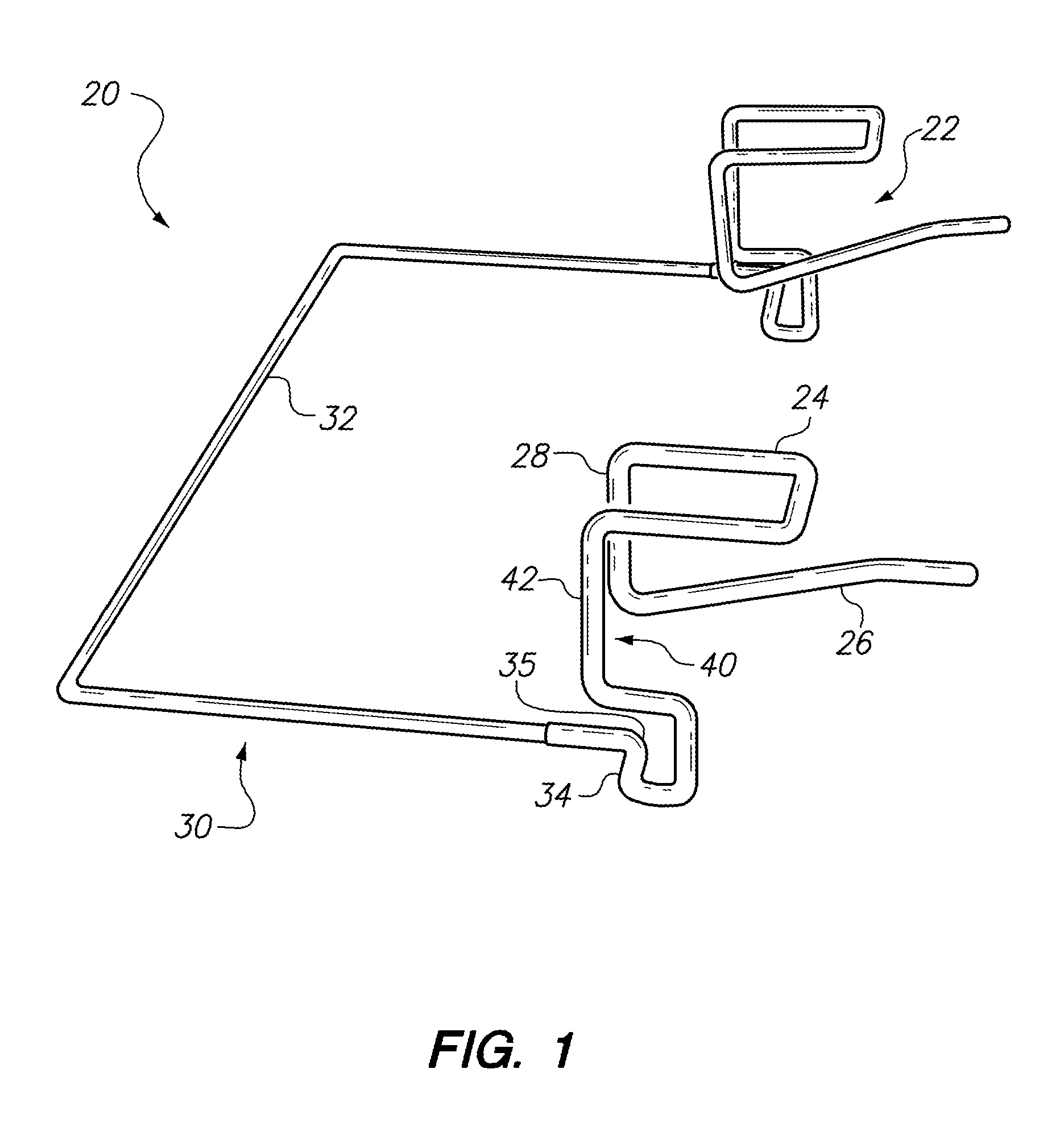
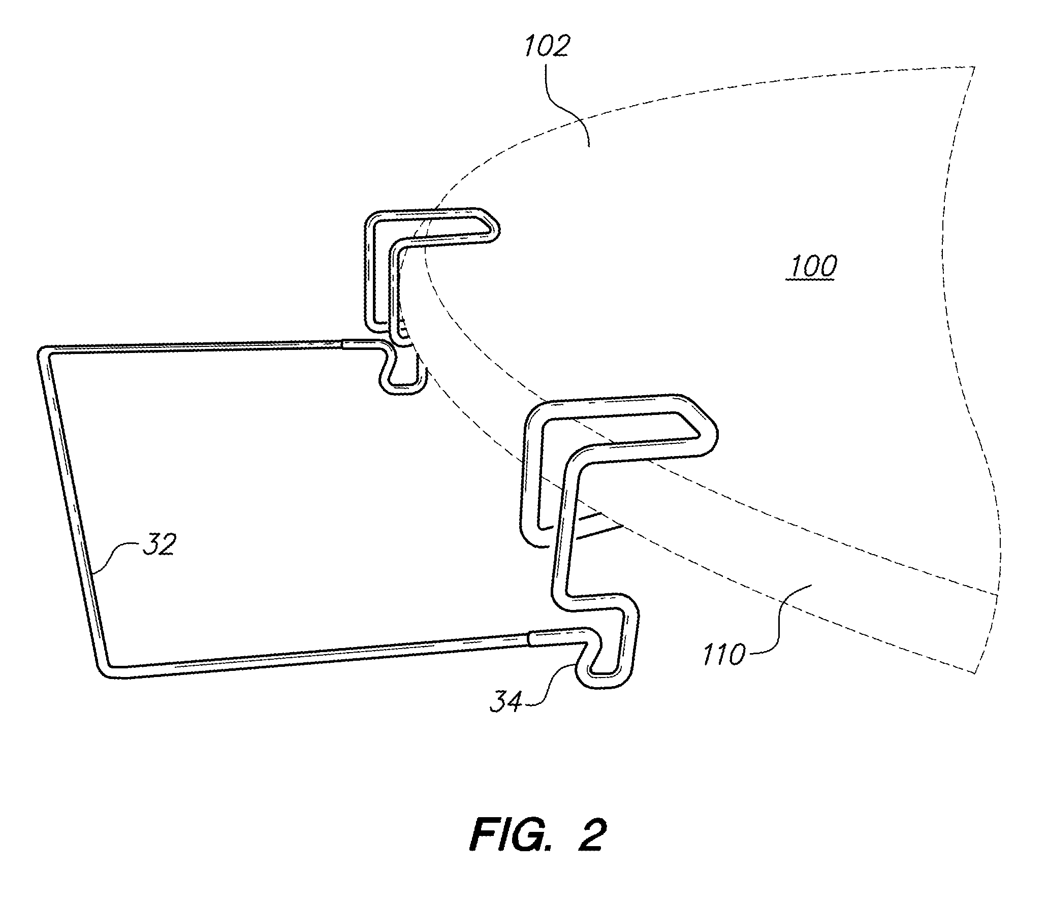
[0052]Referring now to FIGS. 1-4 of the drawings, an apparatus according to a first illustrative embodiment hereof is shown generally at 20. The apparatus 20 is provided for mounting on an edge portion 110 of a table or similar substantially horizontal substrate 100, and for supporting a flexible plastic bag thereon, is shown generally at 20. The apparatus 320 is shown inverted in FIG. 1 for illustrative purposes, and is shown in its normal orientation in FIGS. 2-4.
[0053]The apparatus 20 may include a main body portion formed from bent wire, or alternatively, the main body portion of the apparatus 20 may be formed from a strong plastic material. Where wire is used for forming the main body portion of the apparatus, the main body portion may be formed in multiple parts hinged together so as to be foldable for shipping. In addition, where wire is used for the main body portion, all or part of the wire, particularly a gripping portion thereof may, optionally, be coated with plasti...
second embodiment
[0080
[0081]Referring now to FIG. 9, a gripping portion 222 of a second embodiment of a bag-supporting apparatus 220 is shown, where this embodiment is configured and adapted to be used with a stainless steel countertop having a transverse J-shaped cross-sectional shape as a substrate 110, as shown. Stainless steel countertops of this type are widely used in restaurants and in the food service industry. The bag-supporting apparatus 220 according to the second embodiment is exactly the same as the bag-supporting apparatus 20 according to the first embodiment, except that the two spaced-apart gripping portions 222 have a different configuration from the gripping portions 22 according to the first embodiment.
[0082]Each of the gripping portions 222 in the second embodiment includes an upper horizontal section 224 for placement above the substrate 110. The upper horizontal section 224 may also be formed in a squared-off “U” shape. Each of the gripping portions 222 also includes a lower su...
third embodiment
[0085
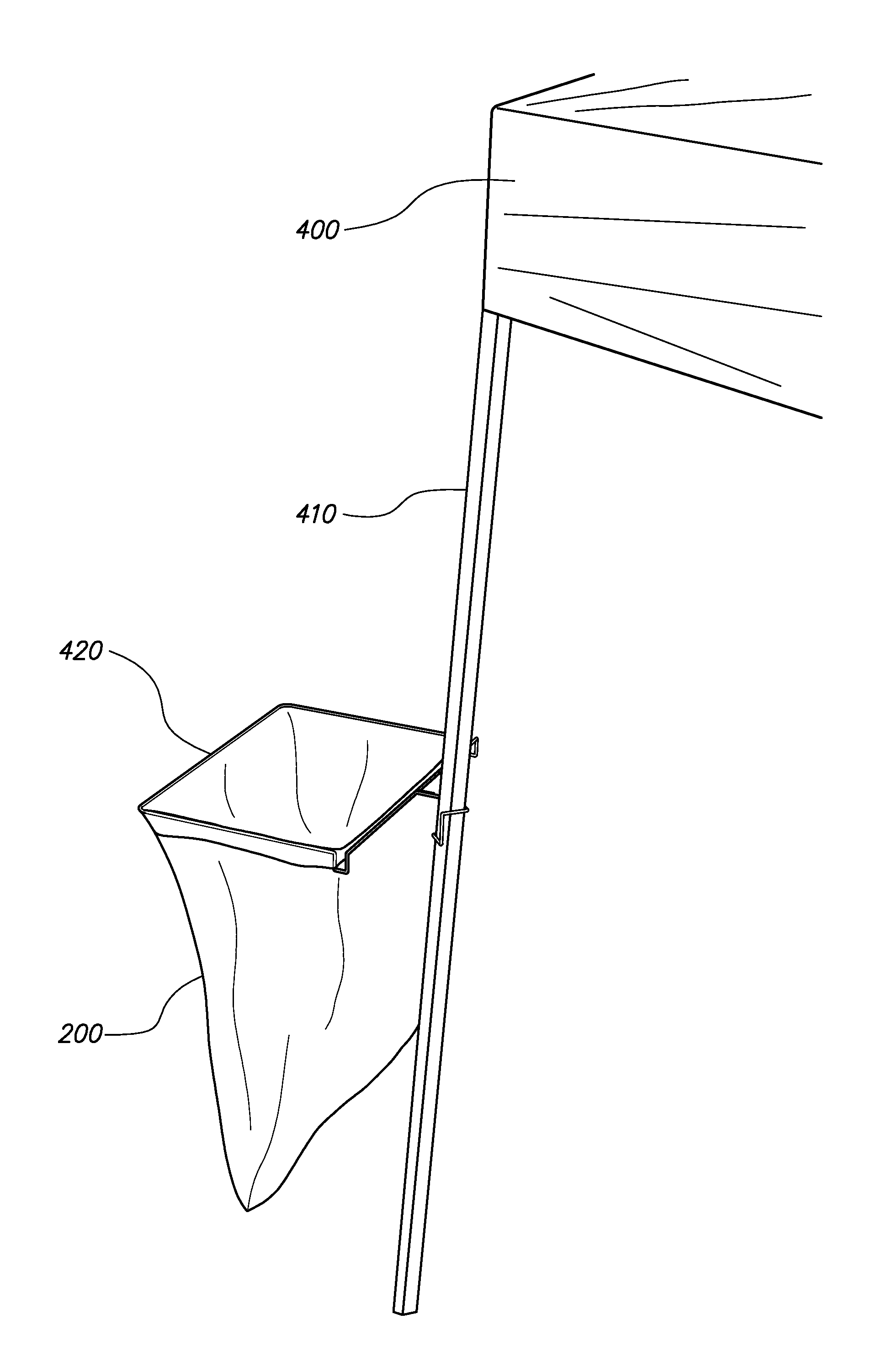
[0086]Another modified embodiment of a bag-supporting frame apparatus according to the present invention may be used to mount a flexible plastic bag on a substantially vertical substrate, such as a wooden fence panel, the top of a door panel, or a closed truck tailgate.
[0087]Referring now to FIGS. 10-13 of the drawings, an apparatus according to a third illustrative embodiment hereof is shown generally at 320. The apparatus 320 is shown inverted in FIG. 10 for illustrative purposes, and is shown in its normal orientation in FIG. 11. The apparatus 320 is provided for mounting on an upper edge portion of a door, fence panel, closed truck tailgate, or similar substantially vertically oriented panel substrate, and for supporting a flexible plastic bag thereon. The apparatus 320 may include a main body portion formed from a single piece of bent wire, or alternatively, the main body portion of the apparatus 320 may be formed from a strong plastic material.
[0088]Where wire is used for...
PUM
 Abstract
Description
Claims
Application Information
 - R&D
- Intellectual Property
- Life Sciences
- Materials
- Tech Scout
- Unparalleled Data Quality
- Higher Quality Content
- 60% Fewer Hallucinations
Browse by: Latest US Patents, China's latest patents, Technical Efficacy Thesaurus, Application Domain, Technology Topic, Popular Technical Reports.
© 2025 PatSnap. All rights reserved.Legal|Privacy policy|Modern Slavery Act Transparency Statement|Sitemap|About US| Contact US: help@patsnap.com