Noise suppression device

a technology of noise suppression and noise reduction, which is applied in the field of noise suppression devices, can solve the problems of reduced voice recognition rate, reduced call voice, and inability to calculate the suppression amount correctly, so as to achieve high-quality noise suppression and prevent excessive suppression

Inactive Publication Date: 2016-06-14
MITSUBISHI ELECTRIC CORP
View PDF8 Cites 0 Cited by
  • Summary
  • Abstract
  • Description
  • Claims
  • Application Information

AI Technical Summary

Benefits of technology

[0014]According to the present invention, the noise suppression device can prevent excessive suppression from being carried out on a sound and can implement high-quality noise suppression.

Problems solved by technology

Because these devices are used in a high-level noise environment in many cases, background noise is also inputted to a microphone together with a voice, and this causes degradation in the call voice, a reduction in the voice recognition rate, and so on.
While the suppression amount is calculated on the basis of the ratio (referred to as the SN ratio from here on) between the power spectrum of the voice and the estimated noise power spectrum in accordance with this conventional noise suppression method, the suppression amount cannot be calculated correctly when the value of the ratio is negative (expressed in decibels).
A problem is that this results in excessive suppression of the low-frequency component of the voice signal, and hence degradation in the voice quality.

Method used


Image

  • Noise suppression device
  • Noise suppression device
  • Noise suppression device

Examples


embodiment 1

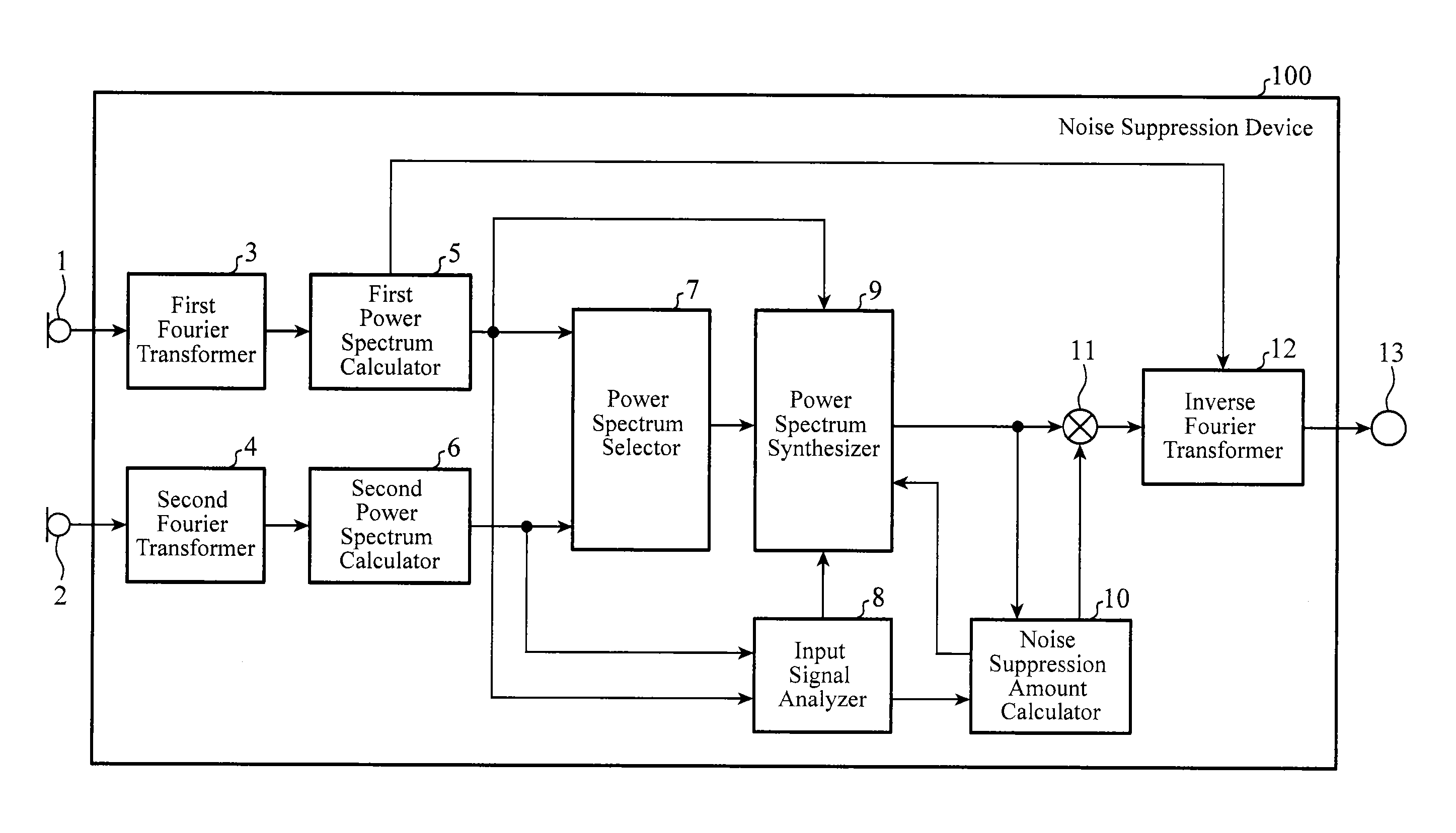
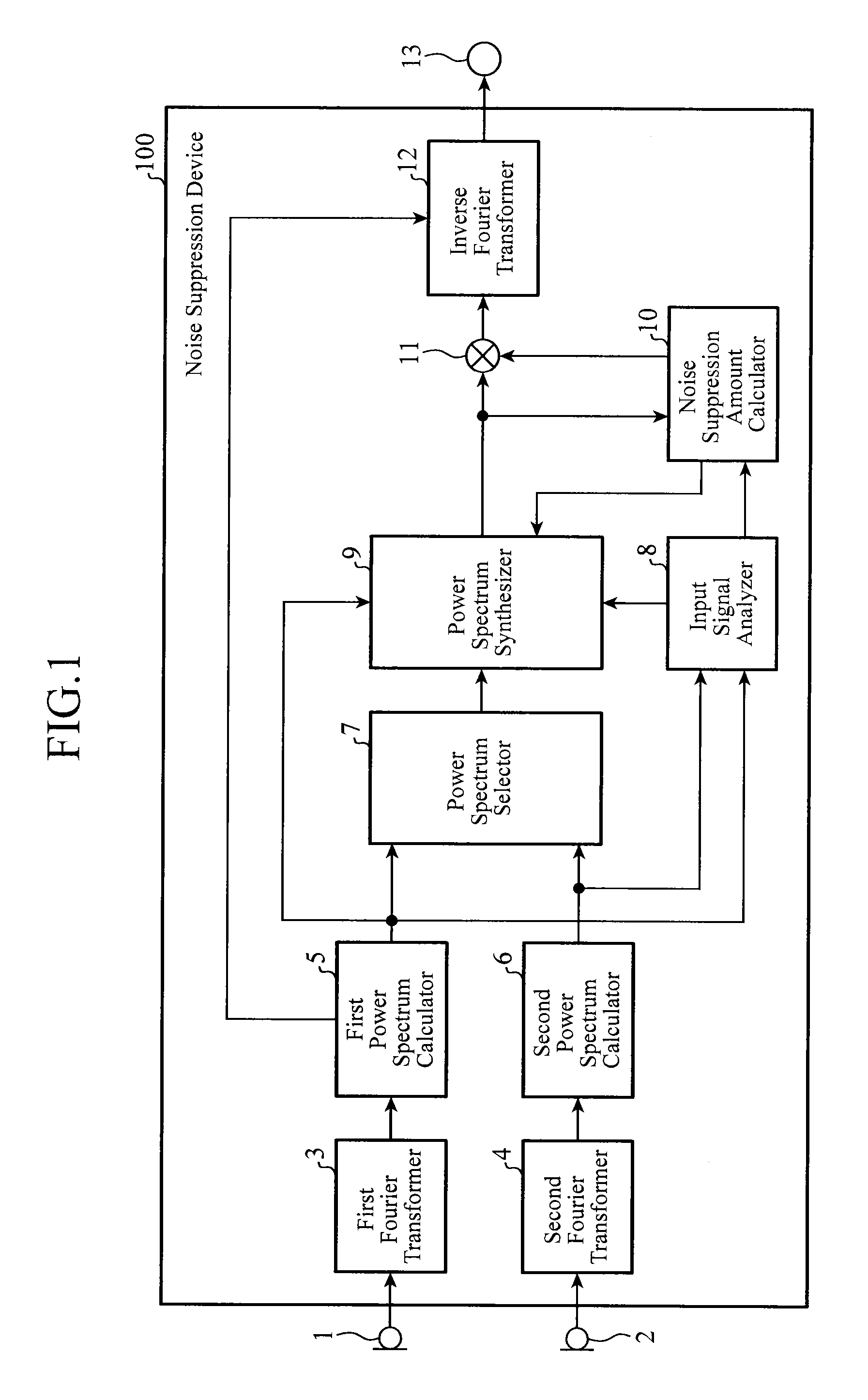
[0028]FIG. 1 is a block diagram showing the structure of a noise suppression device in accordance with Embodiment 1. The noise suppression device 100 to which a first microphone 1 and a second microphone 2 which are input terminals are connected is comprised of a first Fourier transformer 3, a second Fourier transformer 4, a first power spectrum calculator 5, a second power spectrum calculator 6, a power spectrum selector 7, an input signal analyzer 8, a power spectrum synthesizer 9, a noise suppression amount calculator 10, a power spectrum suppressor 11, and an inverse Fourier transformer 12. An output terminal 13 is connected, as a subsequent stage, to the inverse Fourier transformer 12.

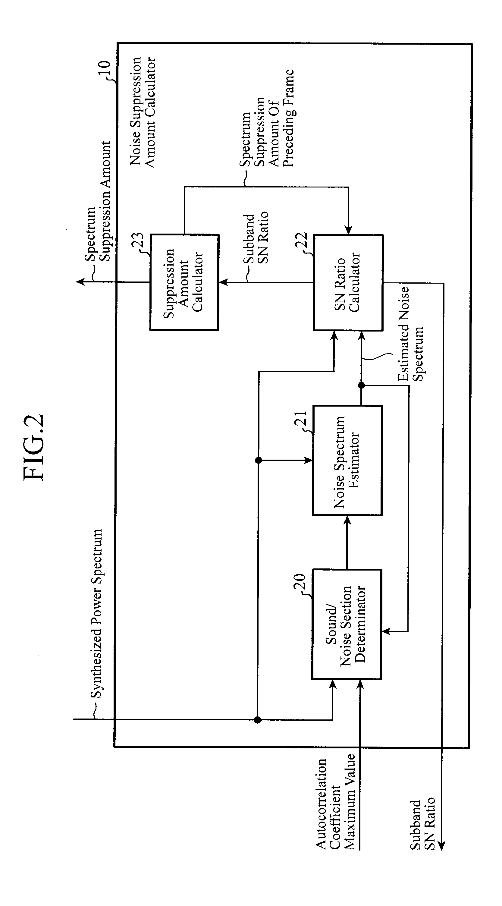
[0029]FIG. 2 is a block diagram showing the structure of the noise suppression amount calculator of the noise suppression device in accordance with Embodiment 1. As shown in FIG. 2, the noise suppression amount calculator 10 is comprised of a sound / noise section determinator 20, a noise spectrum e...

embodiment 2

[0074]In above-mentioned Embodiment 1, the process of changing whether or not (ON / OFF) to carry out the power spectrum synthesis using the above-mentioned equation (8) is carried out on the basis of a comparison between the average snrave(λ) of the subband SN ratios, which is shown in the above-mentioned equation (9), and the predetermined threshold SNRTH. As an alternative, for example, instead of the process of replacing a spectral component, a process of weighted-averaging a synthesized spectrum candidate and a first power spectrum by using this average snrave(λ) as an index showing the degree of sound likeness of the input signal can be carried out, as a power spectrum synthesizing process with a more-continuous change, for a section in which a sound section transitions to a noise section and for a section (transition section) in which a noise section transitions to a sound section, as shown in equation (17) which will be shown below. In Embodiment 2, this structure will be show...

embodiment 3

[0079]Although the structure of setting the value of the limiter A to a predetermined constant in the above-mentioned equation (4) is shown in above-mentioned Embodiment 1, a structure of switching between two or more constants according to an index showing the degree of sound likeness of the input signal to use a constant selected as the value of the limiter, or controlling the value of the limiter by using a predetermined function is shown this Embodiment 3. For example, when the maximum value ρM_max(λ) of the autocorrelation coefficient in the above-mentioned equation (7), as the index showing the degree of sound likeness of the input signal, i.e., a control factor of the state of the input signal, is large, i.e., when the periodical structure of the input signal is clearly seen (there is a high possibility that the input signal is a sound), the value can be set to a large one; otherwise, the value can be set to a small one. Further, the maximum value ρM_max(λ) of the autocorrela...


PUM


Abstract

A noise suppression device includes an input signal analyzer that analyzes the harmonic structure and periodicity of a plurality of input signals on the basis of power spectra of a plurality of input signals, a power spectrum synthesizer that synthesizes the power spectra of the plurality of input signals to generate a synthesized power spectrum according to the result of the analysis by the input signal analyzer, a noise suppression amount calculator that calculates an amount of noise suppression on the basis of the synthesized power spectrum and an estimated noise spectrum estimated from the input signals, and a power spectrum suppressor that carries out noise suppression on the synthesized power spectrum by using the calculated amount of noise suppression.

Description

FIELD OF THE INVENTION[0001]The present invention relates to a noise suppression device that suppresses background noise mixed into an input signal, and that is used for an improvement in the sound quality of a voice communication system, such as a car navigation, a mobile phone, a television phone, or an interphone, a handsfree call system, a TV conference system, a monitoring system, etc., into which, for example, voice communications, a voice storage, and a voice recognition system are introduced, and an improvement in the recognition rate of a voice recognition system.BACKGROUND OF THE INVENTION[0002]As a digital signal processing technology has moved forward in recent years, an operation of making a voice call outdoors using a mobile phone, an operation of making a handsfree phone call in a vehicle, and a handsfree operation using a voice recognition have become popular. Because these devices are used in a high-level noise environment in many cases, background noise is also inp...

Claims


Application Information

Patent Timeline
Patent Type & Authority Patents(United States)
IPC IPC(8): G10K11/16G10L21/0232H04B15/00
CPCG10K11/16G10L21/0232
Inventor FURUTA, SATORU
Owner MITSUBISHI ELECTRIC CORP
Why Eureka
Try Eureka