Ultrasonic diagnosis apparatus

a diagnostic apparatus and ultrasonic technology, applied in ultrasonic/sonic/infrasonic image/data processing, instruments, tomography, etc., can solve the problems of reducing the image quality of ultrasonic images, turbulence of phase misidentification, so as to reduce unnecessary signal components, prevent excessive suppression, and specify the effect of reducing unnecessary signal components

Inactive Publication Date: 2015-11-10
HITACHI LTD
View PDF6 Cites 1 Cited by
  • Summary
  • Abstract
  • Description
  • Claims
  • Application Information

AI Technical Summary

Benefits of technology

[0008]An advantage of the present invention is to prevent excessive suppression with respect to a reception signal while reducing an unnecessary signal component contained in the reception signal.
[0009]Another advantage of the present invention is to comprehensively specify and reduce an unnecessary signal component.
[0010]In accordance with an aspect of the invention, there is provided an ultrasonic diagnosis apparatus including an array transducer which is composed of a plurality of transducer elements; a delay processing unit which performs delay processing with respect to a plurality of element reception signals output from the plurality of transducer elements; a summing processing unit which performs summing processing with respect to the plurality of element reception signals having been subjected to the delay processing; a computing unit which computes an evaluation value based on a sign data array formed of a plurality of sign data items arranged in an element arranging direction, that are extracted from the plurality of element reception signals having been subjected to the delay processing but having not been subjected to the summing processing, the computing unit computing the evaluation value based on a first factor and a second factor which are different from each other, the first factor and the second factor being computed from the sign data array; and a gain adjustment unit which adjusts gain of a reception signal having been subjected to the summing processing, by using the evaluation value.
[0011]With the above structure, the gain of a reception signal after phase alignment and summing processing is adjusted based on an evaluation value. In this case, as the evaluation value is computed based on a first factor and a second factor which reflect the content or structure of a sign data array and which differ from each other, more suitable evaluation value computation in accordance with a situation can be performed as compared with the case where an evaluation value is computed based only on one of these factors. As the first factor and the second factor are computed from the same sign data array, advantages of a reduction in the amount of computation and simplification of the structure can be obtained.
[0012]Preferably, the first factor represents a level of sign coherence in the sign data array, and the second factor represents a sign transit density in the sign data array. An evaluation value is computed based on these two factors.
[0013]When computing the evaluation value only with reference to the sign coherence, the level of the amplitude of each element reception signal and the arranging state of the sign data in the channel direction are not considered. Accordingly, there are cases in which phases are misidentified as being turbulent despite being identical. Further, in the case of computing the evaluation value only with reference to the sign transit density, as the sign transit density changes in accordance with the positional relationship between the strong reflector and the receiving beam origin, there is a possibility that turbulence of phase is misidentified. By referring to both the sign coherence and the sign transit density, the misidentification described above can be prevented or reduced.

Problems solved by technology

However, the beam data actually contain an unnecessary signal component such as a side-lobe component.
However, if the SCF method described above is always applied, there may be a possibility that a main lobe component is excessively suppressed, thereby reducing the image quality of an ultrasonic image.
Accordingly, with the SCF method, there is a possibility that turbulence of the phase is misidentified when the amplitude profile changes across the baseline, despite the amplitude profiles being identical to a certain degree.
Further, in the case of computing the evaluation value only with reference to the sign transit density, as the sign transit density changes in accordance with the positional relationship between the strong reflector and the receiving beam origin, there is a possibility that turbulence of phase is misidentified.

Method used


Image

  • Ultrasonic diagnosis apparatus
  • Ultrasonic diagnosis apparatus
  • Ultrasonic diagnosis apparatus

Examples


Embodiment Construction

[0032]A preferred embodiment of the present invention will be described in detail with reference to the accompanying drawings.

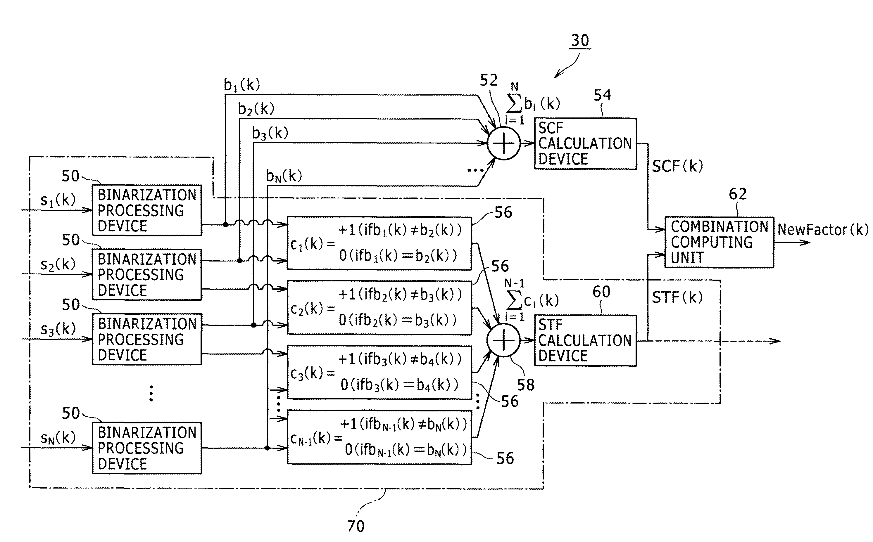
[0033]An ultrasonic diagnosis apparatus according to the present embodiment suppresses an unnecessary or undesired signal component based on an SCF (Sign Coherence Factor) which has been already described above and an STF (Sign Transit Factor) which will be described below. In other words, two methods are used in combination (or selectively). Here, the two methods which are used are not limited to the SCF method and the STF method. By computing an evaluation value on the basis of a plurality of factors which are obtained from different points of view, the content of the evaluation value can be made more appropriate.

[0034]In the following description, a sign data array is formed of a plurality of sign data items which are extracted from a plurality of element reception signals having been subjected to delay processing but not yet having been subjected to summi...


PUM


Abstract

There is provided an ultrasonic diagnosis apparatus capable of reducing an unnecessary signal component in a reception signal. A sign data array formed of a plurality of sign data items arranged in an element arranging direction is extracted from a plurality of element reception signals having been subjected to delay processing but having not been subjected to summing processing. A factor computing unit computes a first factor indicating a level of sign coherence in the sign data array and a second factor indicating a sign transit density in the sign data array. The factor computing unit then computes a factor (evaluation value) for adjusting gain of the reception signal, based on the first factor and the second factor.

Description

BACKGROUND[0001]1. Technical Field[0002]The present invention relates to an ultrasonic diagnosis apparatus, and more particularly to a technique of reducing an unnecessary or undesired signal component such as a side-lobe component, a grating lobe component, or the like, contained in a reception signal.[0003]2. Background Art[0004]Ultrasonic diagnosis apparatuses are apparatuses which form an ultrasonic diagnosis image by transmitting and receiving ultrasound to and from a living organism. In order to increase the image quality of the ultrasonic diagnosis image, it is desirable to reduce an unnecessary signal component contained in a reception signal; i.e., a side-lobe component, a grating lobe component, a noise component, or the like.[0005]More specifically, in a receiving beam former provided in an ultrasonic diagnosis apparatus, for the purpose of focusing, delay processing (phase alignment processing) is applied to a plurality of element reception signals supplied from a plural...

Claims


Application Information

Patent Timeline
Patent Type & Authority Patents(United States)
IPC IPC(8): A61B8/08G10K11/34G01S15/89G01S7/52
CPCA61B8/5269G01S7/52047G01S7/52077G01S15/8915G10K11/346G01S7/52033G01S7/52049
Inventor YOSHIZAWA, SHINGOHISATSU, MASANORI
Owner HITACHI LTD
Why Eureka
Try Eureka