Receiver

Inactive Publication Date: 2007-04-12
RENESAS ELECTRONICS CORP
View PDF11 Cites 101 Cited by
  • Summary
  • Abstract
  • Description
  • Claims
  • Application Information

AI Technical Summary

Benefits of technology

[0015] The Equation (2) suggests that mismatch can be calibrated by adequately selecting the correction coefficients a, b, c, and d even when mismatches of amplitude and phase are added between the input signals Iin and Qin.
[0016] A digital calibration signal outputted from the amplitude/phase mismatch calibrating circuit (GP_CAL) 25 is inputted to the correction coefficient calculating circuit (C_CALC) 21 for detection of IQ mismatch and calculation of corr

Problems solved by technology

In the low IF system, it is known that a problem is generated when the RF received signal in the frequency of fLO+fIF is converted to the IF signal in the frequency of fIF using a local oscillator (hereinafter referred to as “LO”) to generate a local signal in the frequency of fLO.
The known

Method used


Image

  • Receiver
  • Receiver
  • Receiver

Examples


first embodiment

[0059] A first embodiment of the present invention will be explained with reference to FIG. 1 to FIG. 8.

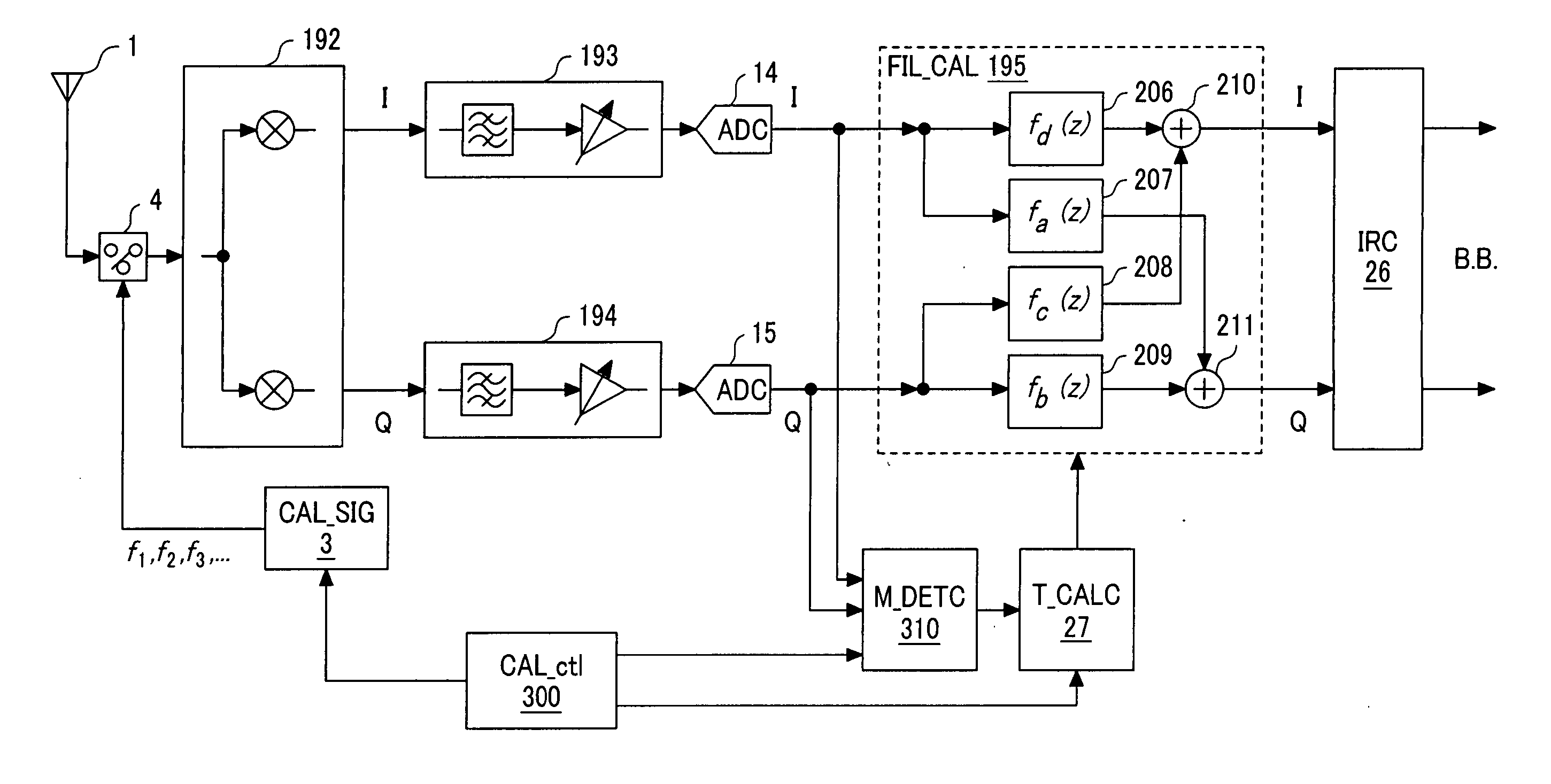
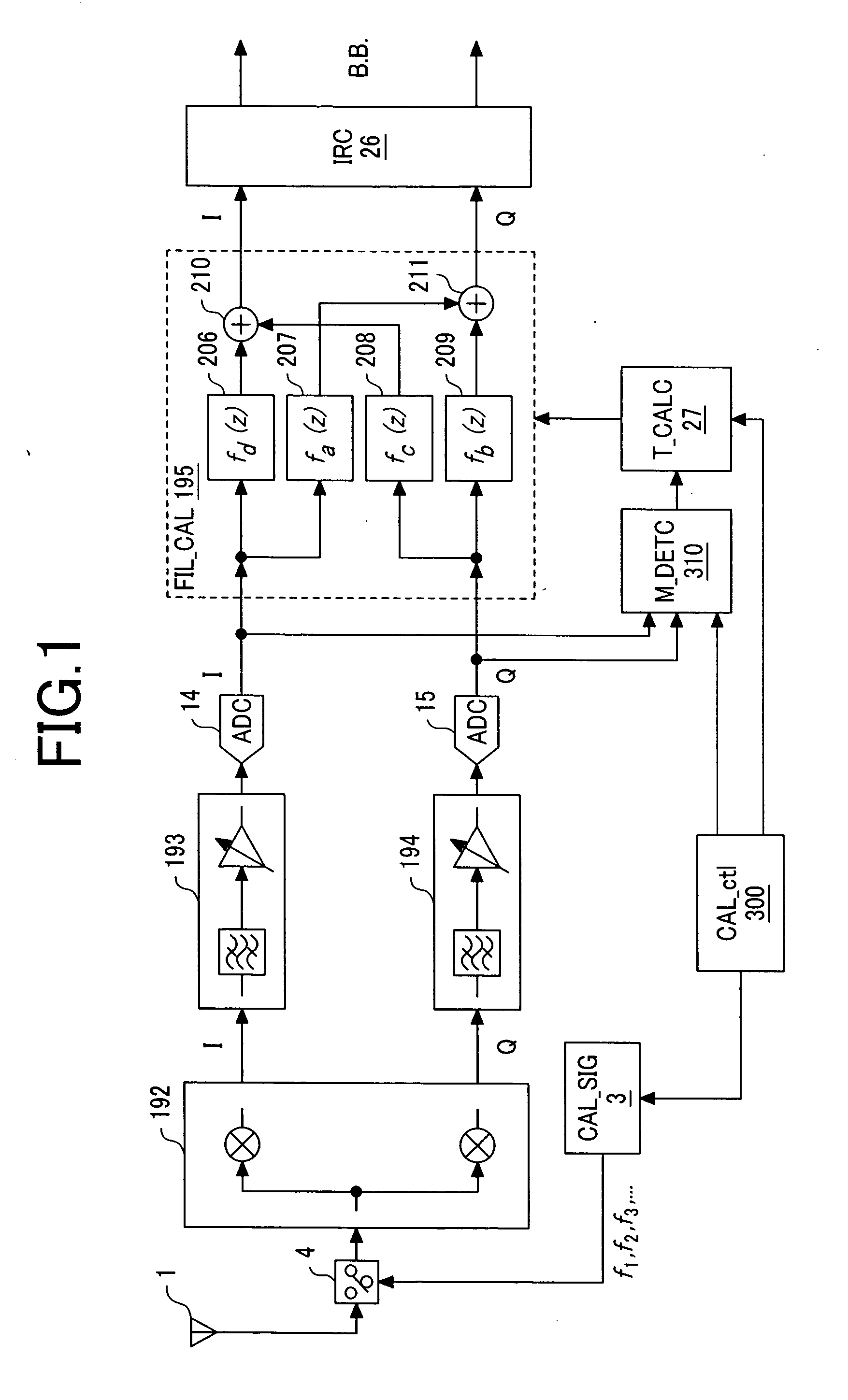
[0060] First, FIG. 1 illustrates an example of structure of a receiver as the first embodiment of the present invention. A low IF receiver illustrated in FIG. 1 comprises an antenna 1, a calibration signal source 3, a switch 4, a quadrature mixer 192, an I component signal path 193, a Q component signal path 194, analog / digital converters (hereinafter referred to as “ADCs” (analog to digital converters)”14, 15, a filter mismatch calibrating circuit (FIL_CAL) 195, an image rejecting circuit (IRC) 26, a tap coefficient calculating circuit (T_CALC) 27, a calibration control circuit (CAL_ctl) 300, and a filter mismatch detecting circuit (M_DETC) 310.

[0061] This embodiment is characterized in comprising a filter mismatch calibrating unit including the calibration signal source 3, switch 4, tap coefficient calculating circuit (T_CALC) 27, filter mismatch calibrating circuit (FIL_CAL) ...

second embodiment

[0109] The second embodiment of the present invention will be described with reference to FIG. 9 to FIGS. 19A and 19B. This embodiment corresponds to a receiver employing the low IF system.

[0110] First, FIG. 9 illustrates a circuit structure of the low IF receiver as the second embodiment of the present invention. The low IF receiver illustrated in FIG. 9 comprises an antenna 1, an LNA 2, a calibration signal source 3, switches 4, 16 to 19, 22, 23, mixers 5, 6, an analog 90° phase shifter 7, an RF synthesizer 8, band-pass filters (BPFs) 9, 10, a control circuit 11, programmable gain amplifiers 12, 13, and analog / digital converters (ADCs) 14, 15. Moreover, the receiver also comprises a filter mismatch calibrating circuit (FIL_CAL) 20, a correction coefficient calculating circuit (C_CALC) 21, a memory (MEM) 24, an amplitude / phase mismatch calibrating circuit (GP_CAL) 25, an image rejecting circuit (IRC) 26, and a tap coefficient calculating circuit (T_CALC) 27.

[0111] This embodiment...

third embodiment

[0180]FIG. 20 shows an example of the other structure of the calibration signal source 3 as the third of the present invention. The calibration signal source 3 shown in the figure is constituted with inclusion of a crystal-controlled oscillator 118, a harmonics generating circuit 161, inverters 123, 124, differential amplifiers 125, 126 and switches 127, 128. The reference signal generated with the crystal-controlled oscillator 118 is inputted to the harmonics generating circuit 161. The harmonics generating circuit 161 of the third embodiment is formed of a PLL (Phase Locked Loop) and a fixed frequency divider with inclusion of a phase comparator (PD) 119, a low-pass filter (LPF) 120, a ring oscillator 121, a variable frequency divider (DIV) 122, and a frequency divider 162. The phase comparator (PD) 119, LPF 120, ring oscillator 121, and variable frequency divider (DIV) 122 form a PLL. In the phase comparator (PD) 119, the frequency of reference signal is compared with the frequen...


PUM


Abstract

The receiver, which enables rejection of image signals with higher accuracy over wider frequency band, can be provided as a low IF receiver by inputting a calibration signal of frequency fi (1≦i≦N) before reception of signals and determining the frequency response fa(z) to fd(z) of a calibrating filter in a filter mismatch calibrating circuit (FIL_CAL) 195 to make zero amplitude and phase mismatches between the I component and Q component of the quadrature demodulation signal at the frequency fIFi.

Description

CLAIM OF PRIORITY [0001] The present application claims priority from Japanese application JP 2005-294444 filed on Oct. 7, 2005, the content of which is hereby incorporated by reference into this application. FIELD OF THE INVENTION [0002] The present invention relates to a receiver and a mobile radio terminal used in a radio system, and particularly to a technology for calibrating, with a plurality of frequencies, amplitude mismatch and phase mismatch between an in-phase (I) component and a quadrature (Q) component in a quadrature demodulation signal. BACKGROUND OF THE INVENTION [0003] In US Patent Application Publication of US 2005 / 0070236 A1, the technology is described for calibrating mismatch using a result on detecting phase and amplitude mismatch of a quadrature demodulation signal in order to realize high precision image rejection in a low IF receiver. Particularly, FIG. 6B of US 2005 / 0070236 A1 illustrates an example of an IQ mismatch correcting circuit. SUMMARY OF THE INVEN...

Claims


Application Information

Patent Timeline
IPC IPC(8): H03M1/10
CPCH03D3/009H04B1/30
Inventor MAEDA, KOJITANAKA, SATOSHIAKAMINE, YUKINORIKAWABE, MANABU
Owner RENESAS ELECTRONICS CORP
Why Eureka
Try Eureka