Implantable medical device, medical system and method for data communication

a medical device and data communication technology, applied in the field of implantable medical devices and data communication, can solve the problems of high current requirements, generally out of the reach of devices, and generally not penetrate the body effectively, and achieve the effects of reducing external components, increasing the signal-to-noise ratio of received communication, and high signal-to-noise ratio

Inactive Publication Date: 2014-08-07
BIOTRONIK SE & CO KG
View PDF5 Cites 98 Cited by
  • Summary
  • Abstract
  • Description
  • Claims
  • Application Information

AI Technical Summary

Benefits of technology

[0034]In at least one embodiment, the external device may receive alterations of impedance that may be modulated to encode data in a binary phase shift key method. The AM demodulated signal, in at least one embodiment, may be encoded in such a manner that there are no long periods in which the implantable medical device switch is in any single position, either on or off. One example of such an encoding scheme may be to encode a logical ‘1’ as modulating the switch closed-open-closed-open and a logical ‘0’ as modulating the switch open-closed-open-closed. In this manner, in at least one embodiment, the switch may be either closed or open twice as long when transitioning from a ‘0’ to ‘1’ or ‘1’ to ‘0’, respectively. The fundamental frequency of switching is thus maintained and narrower band-pass filters may be used in the lock-in amplifier. This in turn may increase signal-to-noise ration of the received communication from the implantable medical device.
[0035]In at least one embodiment, the external device may use two lock-in demodulators phase shifted by 90 degrees. By demodulating the received signal at, for example 0 degrees and 90 degrees, in one or more embodiments, the external device may maintain a high signal-to-noise ratio by combining the two signals. Phase information may a...

Problems solved by technology

Limited battery capacity of an implantable medical device generally calls for energy-efficient data communication.
Such high current requirements are generally out of reach of devices with battery capacities of at most a few hundred mAh.
In addition, RF...

Method used


Image

  • Implantable medical device, medical system and method for data communication
  • Implantable medical device, medical system and method for data communication
  • Implantable medical device, medical system and method for data communication

Examples


Embodiment Construction

[0059]The following description is of the best mode presently contemplated for carrying out at least one embodiment of the invention. This description is not to be taken in a limiting sense, but is made merely for the purpose of describing the general principles of the invention. The scope of the invention should be determined with reference to the claims.

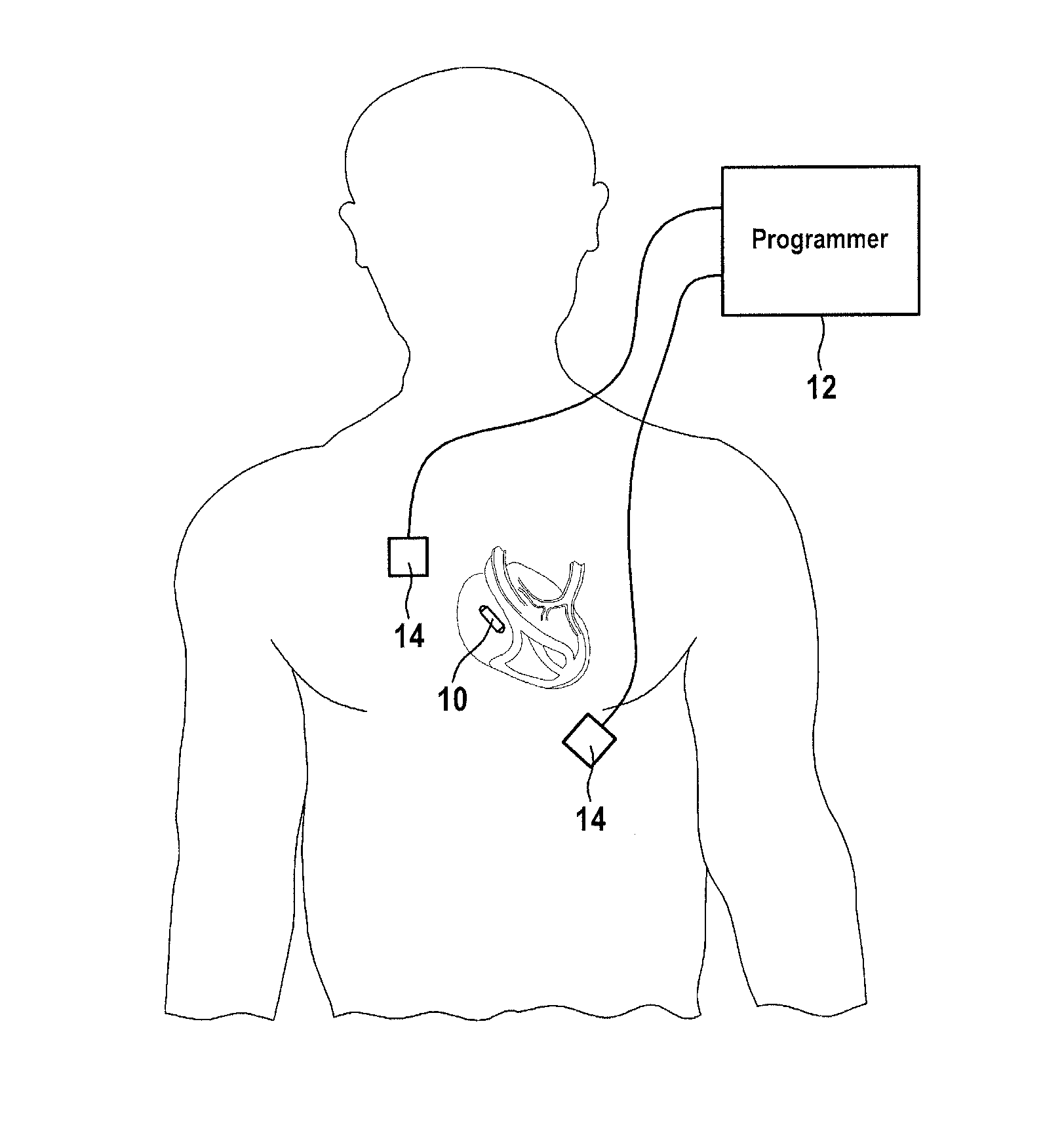
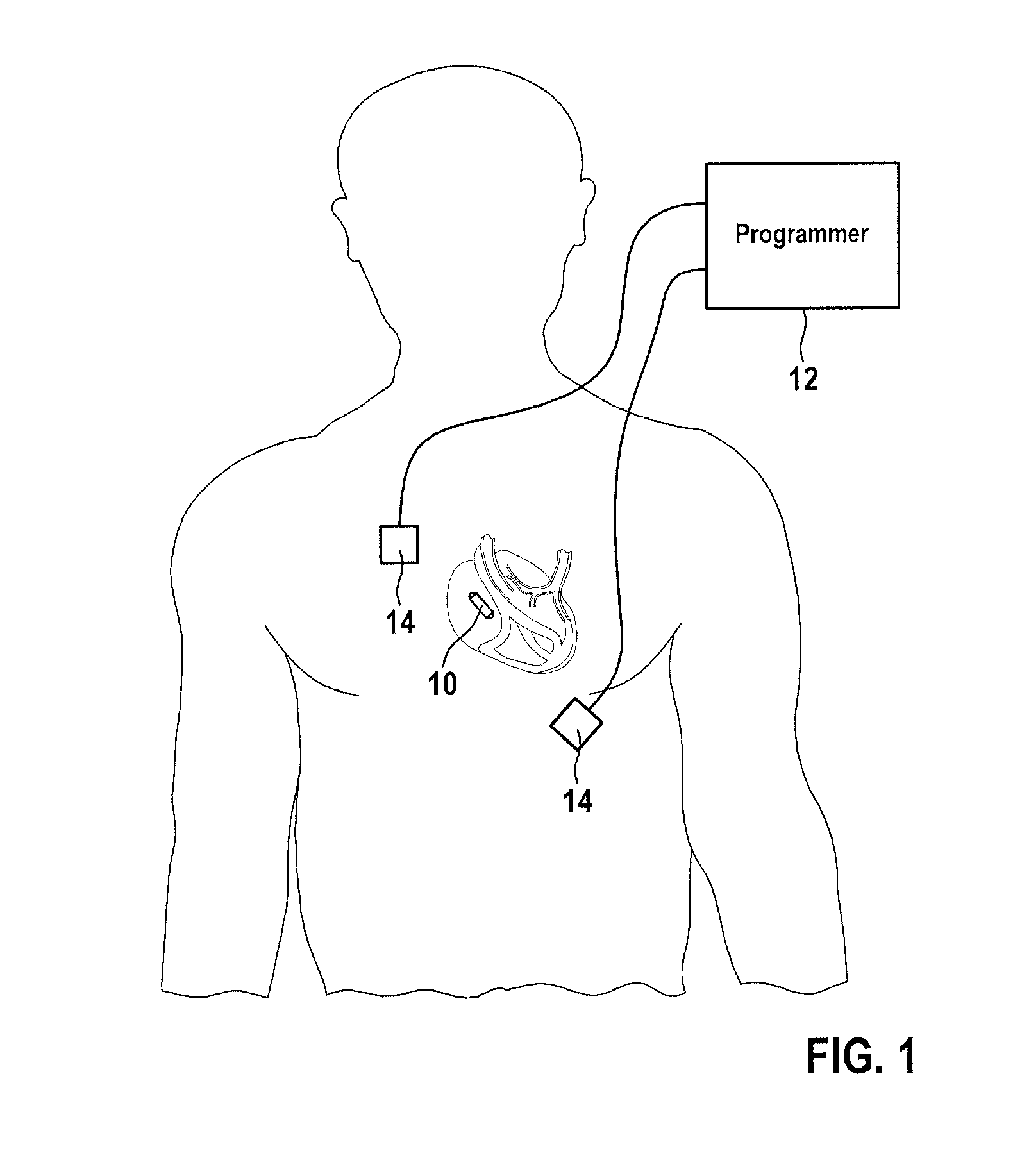
[0060]FIG. 1 shows a representation of a communication system, comprising including an implantable medical device in its implanted state and an external device, according to one or more embodiments of the invention. As shown in FIG. 1, one or more embodiments of the invention, may utilize an implanted pacemaker such as an implantable medical device 10, a programmer or communication device such as external device 12, and cutaneous electrodes 14 that may be placed on either side of the heart. In at least one embodiment, the external device 12 may induce an oscillating electric field between the electrodes between 50 kHz to 1 MHz, pre...


PUM


Abstract

An implantable medical device including a data communication device that includes a device that alters an oscillatory electric field imposed on body tissue surrounding the implantable device. The device that alters an oscillatory electric field modulates an impedance of a conductive medium surrounding the implantable device when the implantable device is within an oscillatory electric field. The device that alters an oscillatory electric field includes a device that generates an oscillatory electric field that is phase-synchronized with an oscillatory electric field imposed on a conductive medium surrounding the implantable device.

Description

[0001]This application claims the benefit of U.S. Provisional Patent Application 61 / 761,707, filed on 7 Feb. 2013, and U.S. Provisional Patent Application 61 / 906,902, filed on 21 Nov. 2013, the specifications of which are hereby incorporated herein by reference.BACKGROUND OF THE INVENTION[0002]1. Field of the Invention[0003]At least one embodiment of the invention generally relates to implantable medical devices and data communication from implantable medical devices to an external device.[0004]2. Description of the Related Art[0005]Typically, implantable devices, in particular implantable medical devices, such as implantable therapy and / or monitoring devices including pacemakers, cardioverters and defibrillators or the like, may include data communication means to transmit data from the implantable medical device to an external device or vice versa. The data communication means, generally, may be used when the implantable medical device is implanted in the body of a mammal or when ...

Claims


Application Information

Patent Timeline
IPC IPC(8): A61N1/372
CPCA61N1/37217A61N1/37211A61N1/37276A61N1/375A61N1/37512A61N1/3708
Inventor MOULDER, J. CHRISTOPHER
Owner BIOTRONIK SE & CO KG
Why Eureka
Try Eureka