Articulated force application for multi-fiber ferrules

a multi-fiber ferrule, articulating force technology, applied in the direction of optics, instruments, optical light guides, etc., can solve the problems of optical fibers losing contact, improper epoxy containment, biased alignment, or both, and adjoining ferrules tilting under load, so as to reduce the side-load component, minimize the side-load component, and facilitate optical fiber insertion

Inactive Publication Date: 2009-06-02
CORNING OPTICAL COMM LLC
View PDF53 Cites 102 Cited by
  • Summary
  • Abstract
  • Description
  • Claims
  • Application Information

AI Technical Summary

Benefits of technology

[0006]In various embodiments, the present invention provides a multi-fiber fiber optic connector assembly in which ferrules and ferrule holders are “force centered” and “balanced,” such that the end faces of the mating ferrules are precisely aligned with one another. In various embodiments, this is accomplished via pivot point and axis selection and ferrule shoulder locations, as is described in greater detail herein below. The present invention also provides a multi-fiber connector assembly that utilizes a “bootless” ferrule. The ferrule of the present invention incorporates a defined attachment point for an articulated force assembly and a back end extension to aide in optical fiber insertion. Force application is provided proximate the front and center of the ferrule (i.e. the center of the fiber array). A “snap” receiving geometry is designed to retain the articulated force assembly without the need for consumables. The articulated joint utilized as an attachment for the ferrule provides a spring seat, a hinge in the x-axis, and a centering mechanism in the y-axis. The centering mechanism in the y-axis minimizes the side-load component and allows the spring to assume its natural angle, for example. The front surface of the ferrule becomes the load-bearing surface. Forces are guided towards the center of the ferrule in the y-axis by a rib structure. Movement in the y-axis is limited by the ferrule geometry, providing a relatively defined position in the multi-fiber fiber optic connector assembly. The hinge in the y-axis allows for movement in the x-axis, reducing the side-load component. The spring tilt is limited by the cavity that the multi-fiber fiber optic connector assembly sits in to prevent direct force coupling to the back end of the ferrule with an excessive out-of-squareness spring. Finally, a pin-keeper may be utilized, “snapped” over the multi-fiber fiber optic connector assembly and engaging the ferrule.

Problems solved by technology

As of yet, there is an unresolved need for a multi-fiber fiber optic connector assembly that minimizes problems associated with off-center force application, which may load one end of a fiber array more than the other end, ultimately causing some optical fibers to lose contact (this problem contributed to by the co-planarity deviations experienced during manufacturing).
Alignment issues between the plug housing and the mating ferrule (i.e. different angles of engagement) may contribute to this side-load component, as well as misalignment due to manufacturing tolerances.
Further, the discrete design of a multi-fiber ferrule and boot requires the handling of two parts and allows for assembly tolerances, potentially leading to improper epoxy containment, biased alignment, or both.
The y-axis, however, may introduce a significant moment, causing adjoining ferrules to tilt under load.
The reduction of overall force and consequential deformation within a row also reduce the ability to compensate for co-planarity tolerances.

Method used


Image

  • Articulated force application for multi-fiber ferrules
  • Articulated force application for multi-fiber ferrules
  • Articulated force application for multi-fiber ferrules

Examples


Embodiment Construction

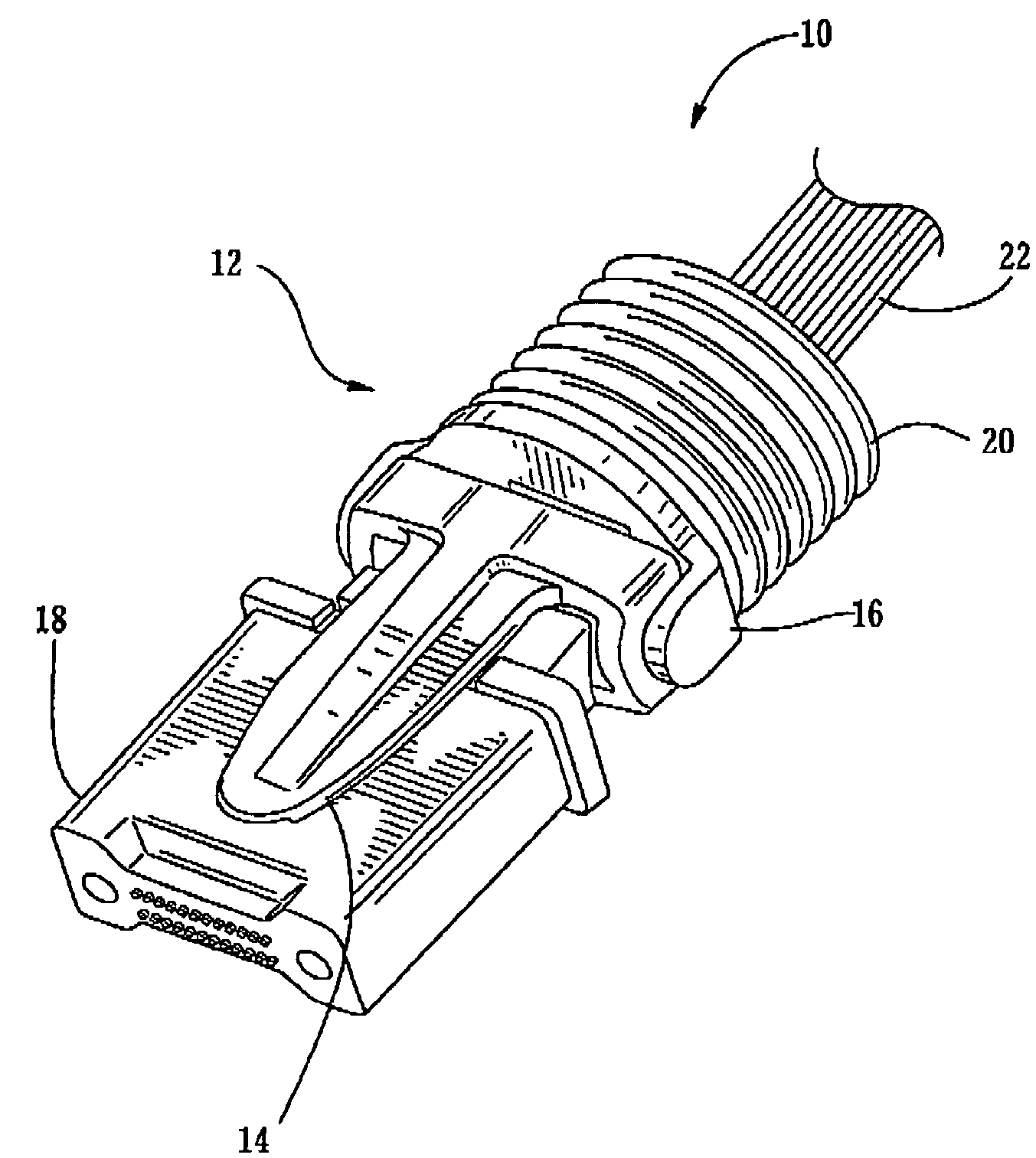
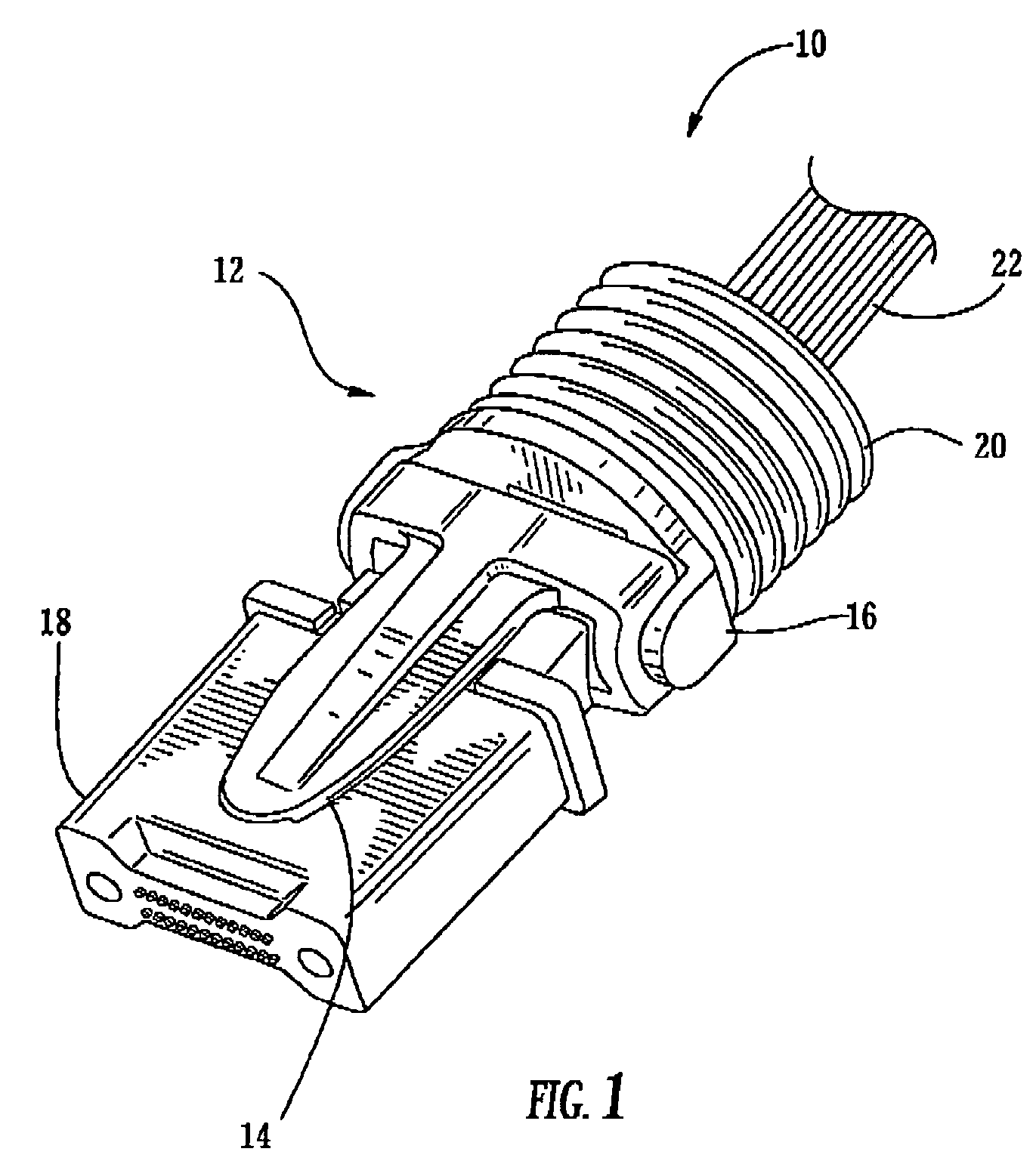
[0024]In various embodiments, the present invention provides a multi-fiber fiber optic connector assembly in which the ferrules and ferrule holders are “force centered” and “balanced,” such that the end faces of the ferrules are precisely aligned with one another. This is accomplished via pivot point and axis selection and ferrule shoulder locations, as is described in greater detail herein below. The present invention also provides a multi-fiber fiber optic connector assembly that utilizes a “bootless” ferrule. The ferrule of the present invention incorporates a defined attachment point for an articulated force assembly and a back end extension to aide in optical fiber insertion. Force application is provided proximate the front and center of the ferrule (i.e. the center of the fiber array). A “snap” receiving geometry is designed to retain the articulated force assembly without the need for consumables. The articulated joint utilized as an attachment for the ferrule provides a spr...


PUM


Abstract

The present invention provides a multi-fiber fiber optic connector assembly providing articulated force application, including: a ferrule holder including an x-pivot component and a y-pivot component, wherein the x-pivot component of the ferrule holder is operable for providing relative rotational movement about the x-axis of the multi-fiber fiber optic connector assembly and the y-pivot component of the ferrule holder is operable for providing relative rotational movement about the x-axis of the multi-fiber fiber optic connector assembly; a multi-fiber ferrule comprising a plurality of optical connection points coupled to the ferrule holder; and a biasing member coupled to the ferrule holder and the multi-fiber ferrule, wherein the biasing member is operable for transferring a force through the ferrule holder and to the multi-fiber ferrule, and wherein the y-pivot component of the ferrule holder is coupled to the biasing member, the x-pivot component of the ferrule holder is coupled to the y-pivot component of the ferrule holder, and the multi-fiber ferrule is coupled to the x-pivot component of the ferrule holder.

Description

BACKGROUND OF THE INVENTION[0001]1. Field of the Invention[0002]The present invention relates generally to fiber optic connector assemblies, and more specifically, to articulated force application systems and methods for multi-fiber ferrules that take advantage of pivot point and axis selection and ferrule shoulder locations.[0003]2. Technical Background of the Invention[0004]Fiber optic connector assemblies including multi-fiber ferrules are used to interconnect optical fibers and devices within optical networks. Cable assemblies and network connection terminals in said networks often include receptacles for receiving connectors, such as multi-fiber connectors. Receptacles typically include receptacle housings defining internal cavities that house alignment structure for receiving and aligning a ferrule within the receptacle to a corresponding ferrule of a fiber optic connector. In some assembly examples, the alignment structure may assist in the gross alignment of the ferrules, wh...

Claims


Application Information

Patent Timeline
Patent Type & Authority Patents(United States)
IPC IPC(8): G02B6/38
CPCG02B6/3821G02B6/3885
Inventor LUTHER, JAMES PHILLIPTHEUERKORN, THOMAS
Owner CORNING OPTICAL COMM LLC
Why Eureka
Try Eureka