Display and timing controller

a timing controller and display technology, applied in the field of display and timing controllers, can solve problems such as difficulty in employing l-configuration, and achieve the effect of minimizing emi and improving signal waveform

Inactive Publication Date: 2006-11-16
MITSUBISHI ELECTRIC CORP
View PDF4 Cites 32 Cited by
  • Summary
  • Abstract
  • Description
  • Claims
  • Application Information

AI Technical Summary

Benefits of technology

[0011] An object of the present invention is to provide a timing controller and a display capable of achievin...

Problems solved by technology

However, it is often difficult to employ the L-config...

Method used


Image

  • Display and timing controller
  • Display and timing controller
  • Display and timing controller

Examples


first preferred embodiment

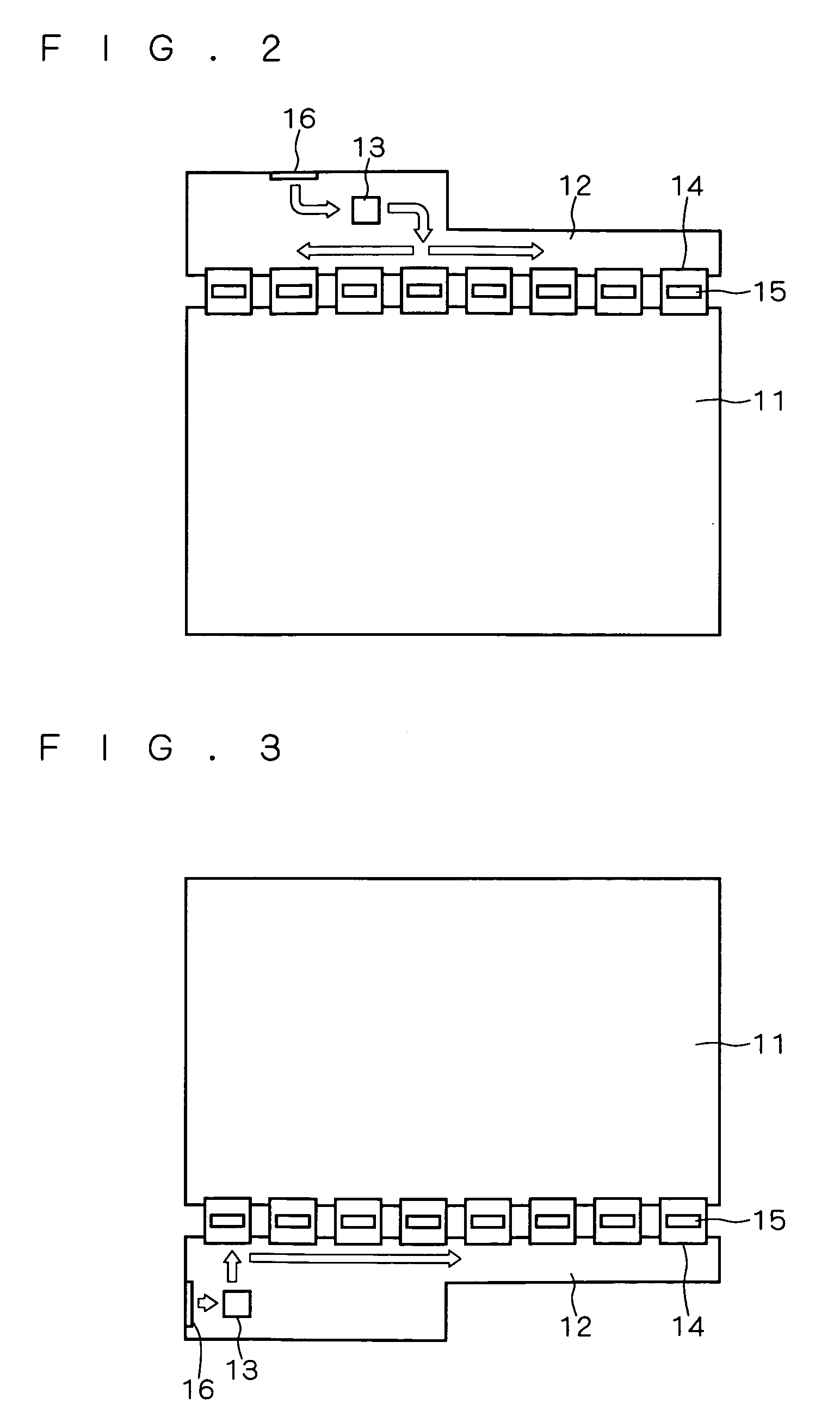
[0024] For the sake of convenience, a conventional display will be described prior to discussing the present invention. FIGS. 2 to 4 are diagrams each illustrating a specific structure of a conventional display.

[0025] In the example shown in FIG. 2, column drivers 15 for driving a display panel 11 are each mounted on a TCP (Tape Carrier Package) or COF (Chip on Film) 14 (hereinafter referred to as “TCP / COF 14”), and the TCP / COF 14 is connected to the display panel 11 and a circuit board 12 through an anisotropic conductive film (ACF), respectively. In this example, the display has eight column drivers 15. This case corresponds to, for example, the use of column drivers, each having 384 outputs (RGB data of 128 pixels), for driving an XGA display panel (1024×768 pixels). TCP / COFs 14 each having the column driver 15 mounted thereon are arranged on one side of the display panel 11. A T-CON 13 is mounted on the circuit board 12, and is positioned taking into account the positional rela...

second preferred embodiment

[0060] As already described, the T- and L-configurations each have a different number of termination resistors. Therefore, to equalize the amplitude of a transmitted signal in the both configurations, the T-CON output current needs to be varied. More specifically, the T-configuration requires nearly twice the current in the L-configuration.

[0061] Further, an output current of T-CON output buffers directly affects the amplitude of a signal transmitted via the clock line and data line, and therefore, needs to be minimized to the extent possible within a range that satisfies input specifications for the column drivers in order to reduce EMI.

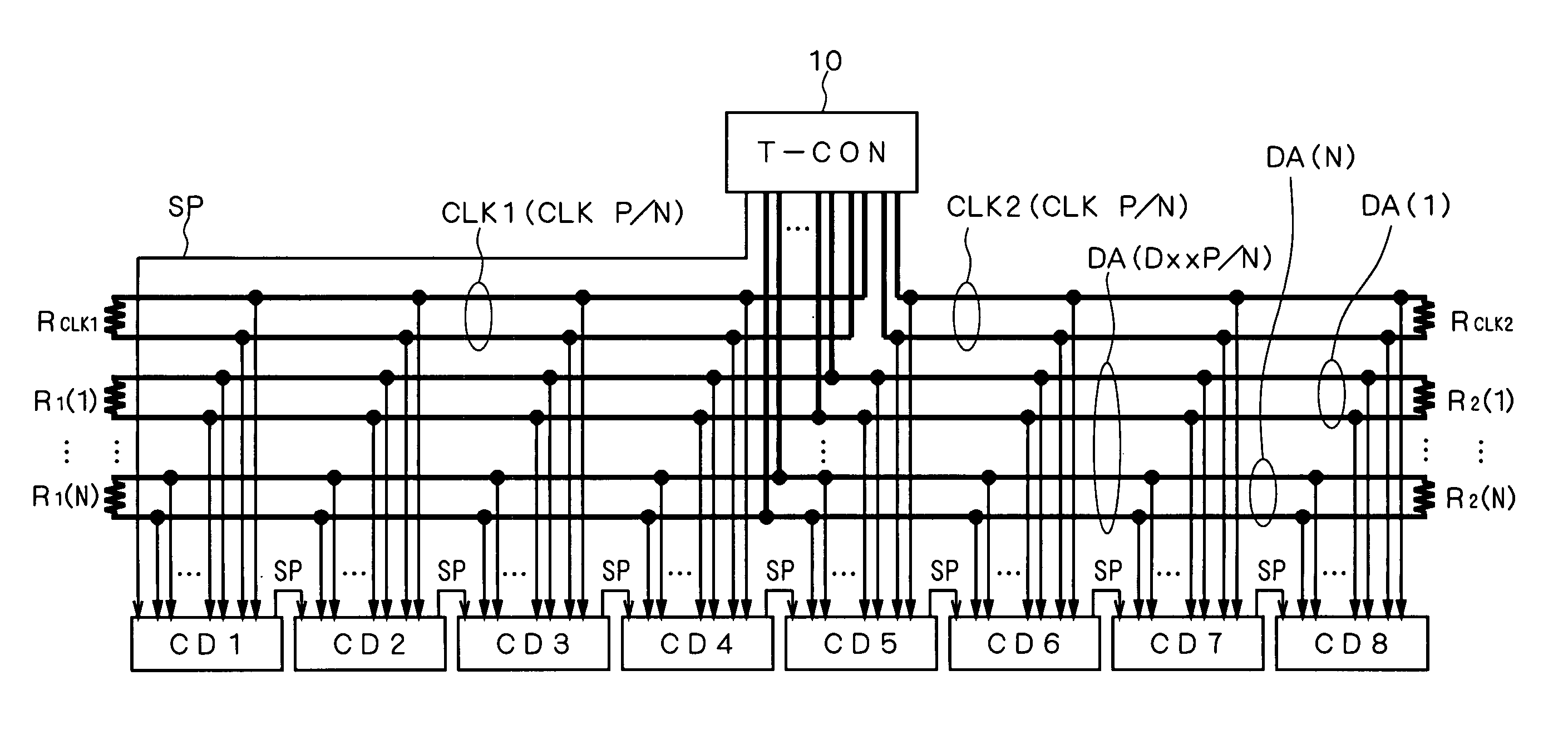
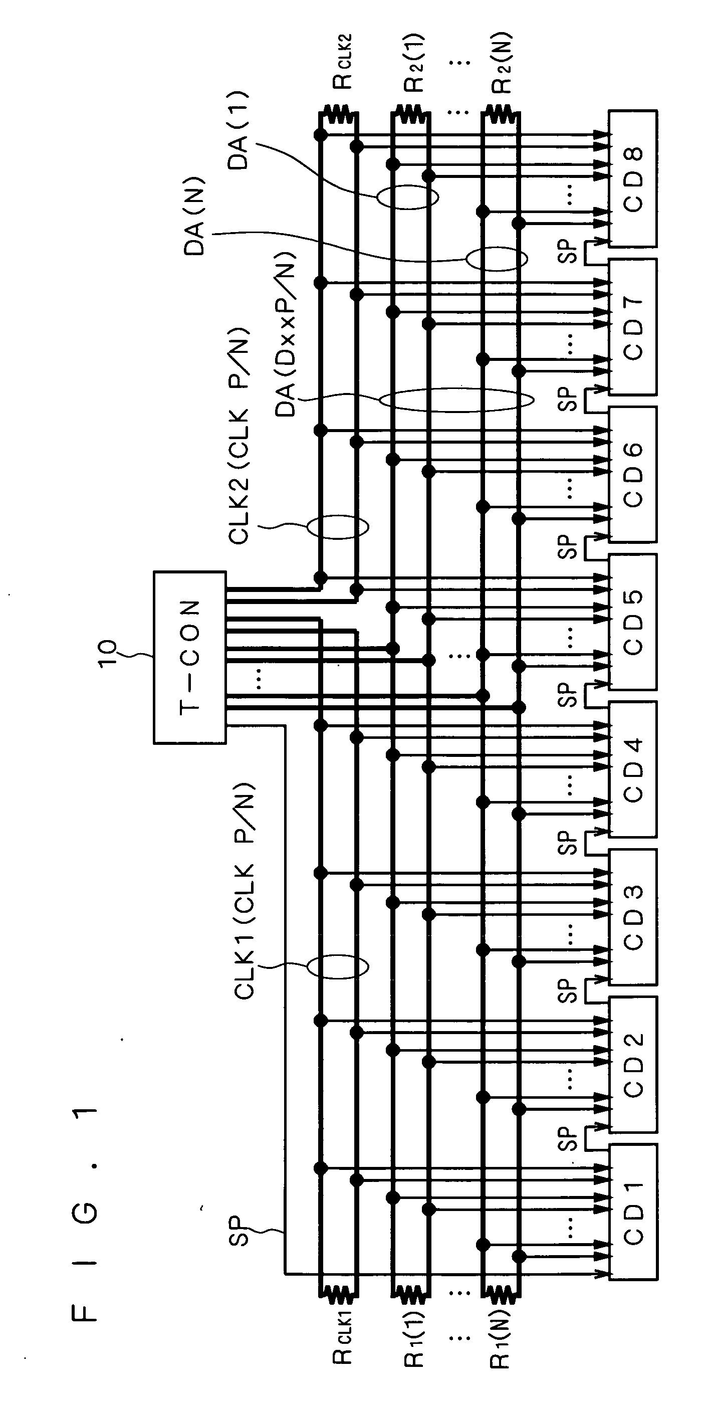
[0062] The T-CON 10 according to the first preferred embodiment is assumed to have its dual clock output ports connected to the L-configuration buses (clock lines CLK1, CLK2) and its data output ports connected to the T-configuration buses (data lines DA), as shown in FIG. 1. Accordingly, in this preferred embodiment, the T-CON 10 according to the...


PUM


Abstract

In a display, column drivers each drive a display panel based on a clock signal and image data signals out of a timing controller. The timing controller has dual clock output ports for outputting the same clock signal and at least one clock output port for outputting image data signals. Each of the column drivers is connected to either of the dual clock output ports via a first or second clock line of L-configuration, and the data output port is connected to all of the column drivers via data lines of T-configuration.

Description

BACKGROUND OF THE INVENTION [0001] 1. Field of the Invention [0002] The present invention relates to a display and a timing controller mounted thereon, and more particularly, to a signal transmission technology employing a differential signal transmission method. [0003] 2. Description of the Background Art [0004] Displays such as liquid crystal displays are provided with a timing controller (hereinafter referred to as “T-CON”) for supplying a clock signal and image data signals synchronized with the clock signal to column drivers (CDs) for driving a display panel. For signal transmission from the T-CON to the column drivers, a transmission method using differential signals (hereinafter referred to as “a differential signal transmission method”) such as a mini-LVDS (Low Voltage Differential Signaling) or RSDS™ (Reduced Swing Differential Signaling) interface technology has widely been used for fewer traces and minimized Electro-magnetic Interference (hereinafter referred to as “EMI”)...

Claims


Application Information

Patent Timeline
IPC IPC(8): G09G5/00
CPCG09G2330/06G09G3/2092G09G3/20G02F1/133G09G3/36
Inventor TASHIRO, TOMOHIRO
Owner MITSUBISHI ELECTRIC CORP
Why Eureka
Try Eureka