
Aircraft engine

Pending Publication Date: 2022-08-25
LILIUM EAIRCRAFT GMBH
View PDF0 Cites 0 Cited by
  • Summary
  • Abstract
  • Description
  • Claims
  • Application Information

AI Technical Summary

Benefits of technology

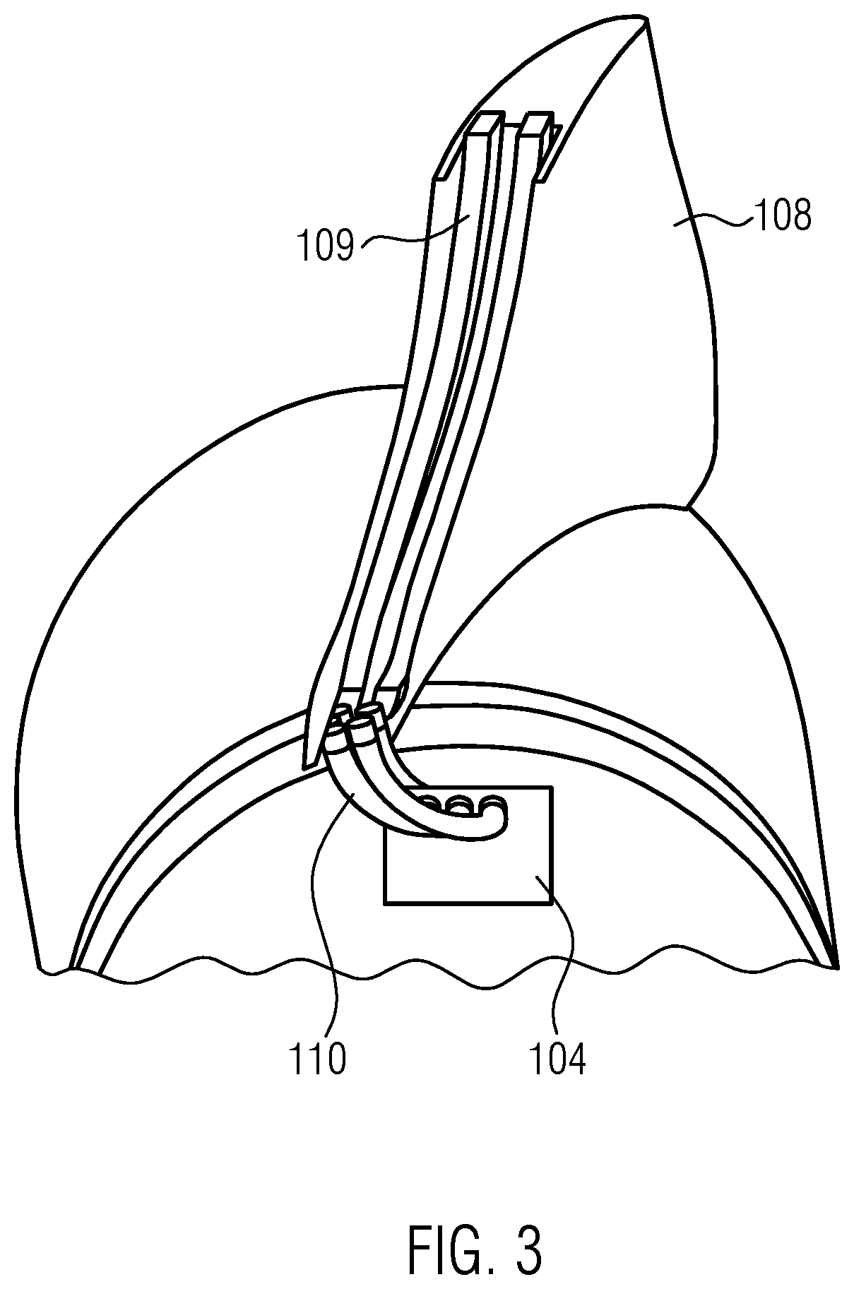
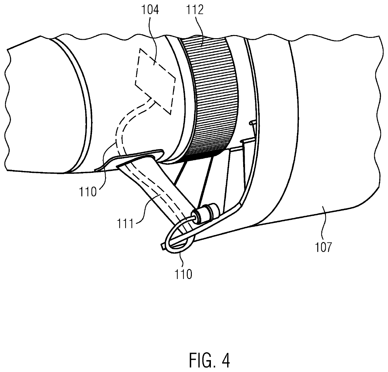
The present disclosure provides an engine for an aircraft that includes a rotor, an electric motor actuating the rotor, and an electronic control unit (ECU) for controlling the electric motor. The ECU is located within the volume of the main air flow caused by the rotor, reducing the distance between the ECU and the electric motor and minimizing interference. The engine design is compact, reducing weight and material requirements. The engine may also include a hub and a stator, and the ECU may be integrated within the hub or downstream of the compression section of the engine. The engine may also include one or more hollow pylons that house at least part of the cabling of the ECU. The technical effects of the present disclosure include reducing EMI, minimizing weight and material requirements, and improving cooling.

Problems solved by technology

First of all, this solution requires long cabling from the ECU to the electric motor, thus increasing EMI.
Moreover, for large ECU comprising several components and several Printed Circuit Boards (PCBs), the available volume at the side of the engine may lead to complex form factors and thus to heavier casings and complex assembly sequences.
Furthermore, the cooling capacity available on the side of the engine may be limited.

Method used


Image

  • Aircraft engine
  • Aircraft engine
  • Aircraft engine

Examples


Embodiment Construction

[0033]Hereinafter, the present disclosure is described with reference to particular embodiments, as illustrated in the attached figures. However, the present disclosure is not limited to the particular embodiments described in the following detailed description and represented in the figures, but rather the described embodiments simply exemplify the various aspects of the present disclosure, the purpose of which is defined by the claims. Further modifications and variations of the present disclosure will be clear to those skilled in the art.

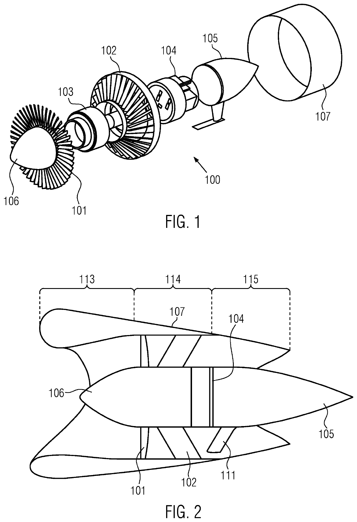
[0034]FIG. 1 schematically shows an exploded view of an engine 100 according to an embodiment of the present disclosure.

[0035]The engine 100 comprises a rotor 101 and a stator 102. The rotation of the rotor 101 provides a main flow of air causing the thrust of the engine 100. The engine 100 further comprises an electric motor 103 that actuates the rotation of the rotor 101. The electric motor 103 may operate on the basis of magnets and coils in a...


PUM


Abstract

An engine for an aircraft is presented comprising a rotor, an electric motor actuating the rotation of the rotor and an ECU controlling the electric motor, wherein the rotation of the rotor provides a main flow of air causing the thrust of the engine and wherein the ECU is located within the volume defined by the main flow.

Description

CROSS-REFERENCE TO RELATED APPLICATION[0001]Pursuant to 35 U.S.C. § 119(a), this application claims the benefit of the filing date of European Patent Application Serial No. EP21158167.3, filed Feb. 19, 2021, for “Aircraft Engine,” the disclosure of which is hereby incorporated herein in its entirety by this reference.TECHNICAL FIELD[0002]The present disclosure relates to the field of engines. In particular, the present disclosure relates to the field of aircraft engines. Still more, in particular, the present disclosure relates to the field of electrically driven aircraft engines.BACKGROUND[0003]Electrically driven aircraft engines are used nowadays for the propulsion of aircrafts. For example, US 2020 / 0198792 A1, US 2019 / 0203735 A1 and WO 2019 / 243767 A1 describe aircrafts comprising electrically driven propulsors. Moreover, such electrically driven engines are also used for vertical take-off and landing (vtol) aircrafts, wherein the electrically driven engines are configured both t...

Claims


Application Information

Patent Timeline
IPC IPC(8): B64D27/24
CPCB64D27/24B64C11/001B64U50/19B64D27/404B64D27/40B64D33/00Y02T50/40Y02T50/60B64D31/00
Inventor VERMEIREN, SEBASTIEN
Owner LILIUM EAIRCRAFT GMBH
Learn More