
High dielectric antenna array

a high dielectric antenna array and antenna array technology, applied in the field of wireless signal transmission, to achieve the effect of decreasing the distance between individual antennas and reducing the size of an array

Inactive Publication Date: 2015-02-12
OSSIA
View PDF6 Cites 246 Cited by
  • Summary
  • Abstract
  • Description
  • Claims
  • Application Information

AI Technical Summary

Benefits of technology

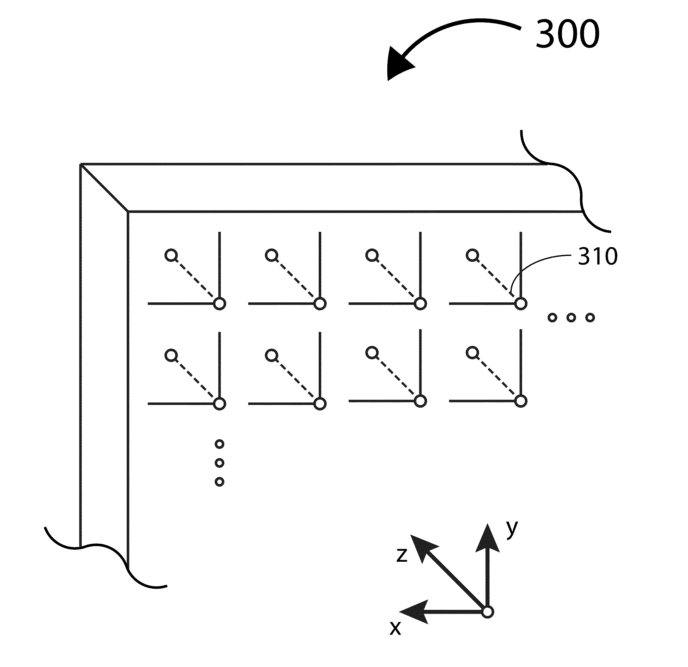
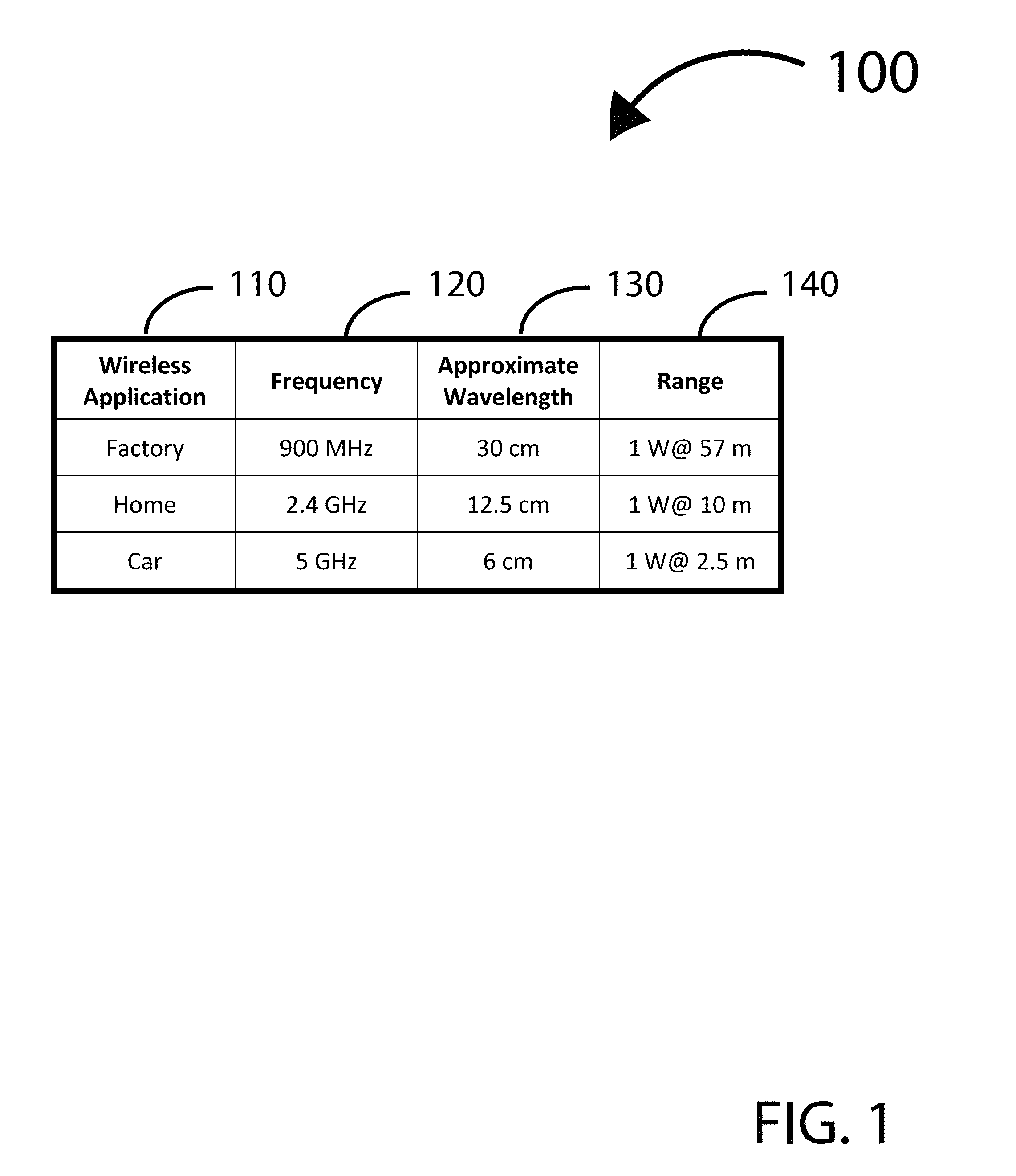
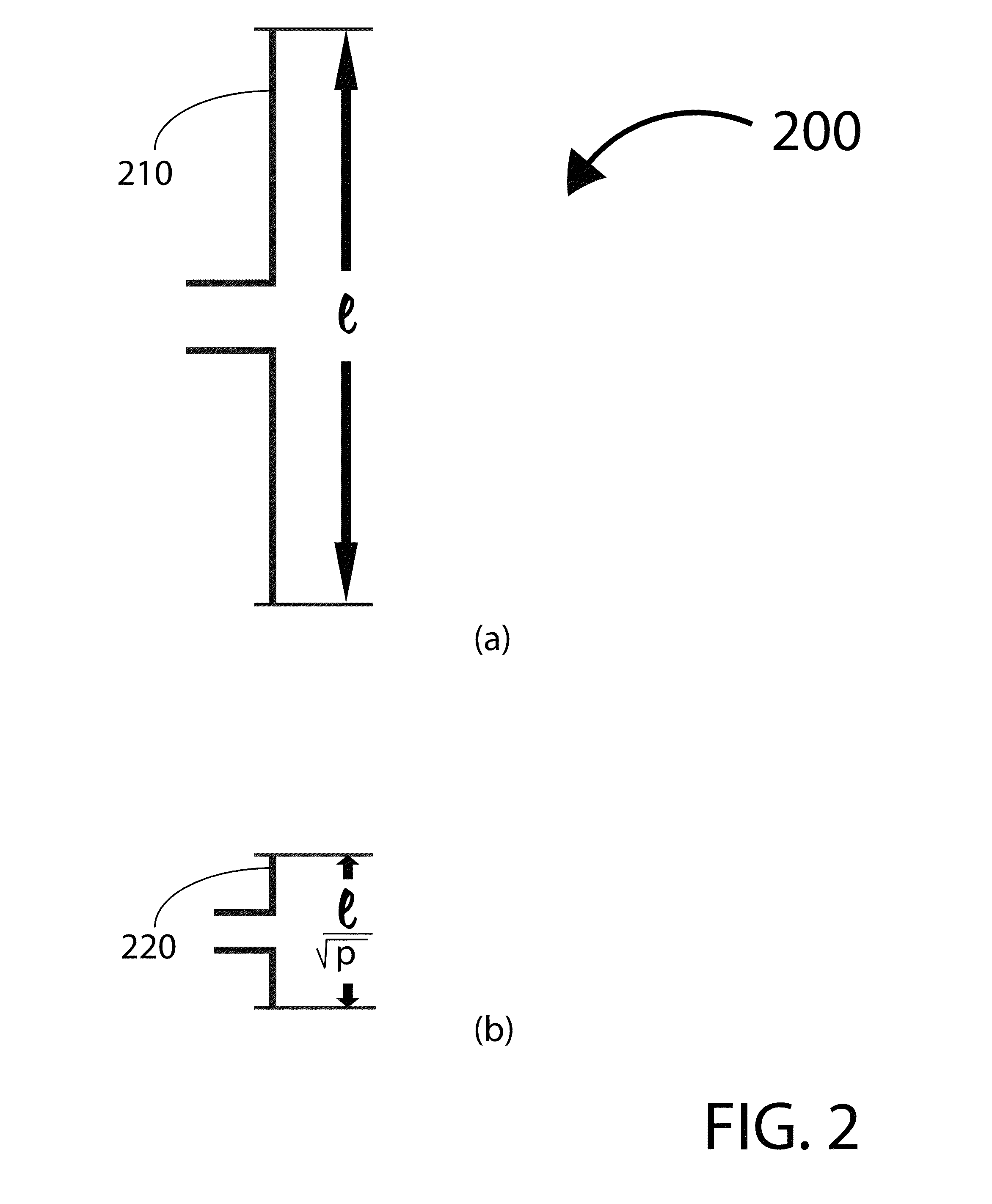
This patent describes a way to make a smaller array of antennas while keeping them away from each other. This is done by using a high dielectric material to decrease the distance between the antennas, and arranging them at right angles to each other to prevent interference. Additionally, wires are covered in high dielectric material to refract RF signals, allowing the antennas to successfully transmit signals past layers above them. Overall, this results in a more efficient use of space and improved performance of the antenna array.

Problems solved by technology

However, placing 1 million antennae within more or less the same distance of 5 meters from the target is a challenge.

Method used


Image

  • High dielectric antenna array
  • High dielectric antenna array
  • High dielectric antenna array

Examples


Embodiment Construction

[0024]The present invention will now be described in detail with reference to several embodiments thereof as illustrated in the accompanying drawings. In the following description, numerous specific details are set forth in order to provide a thorough understanding of embodiments of the present invention. It will be apparent, however, to one skilled in the art, that embodiments may be practiced without some or all of these specific details. In other instances, well known process steps and / or structures have not been described in detail in order to not unnecessarily obscure the present invention. The features and advantages of embodiments may be better understood with reference to the drawings and discussions that follow.

[0025]Aspects, features and advantages of exemplary embodiments of the present invention will become better understood with regard to the following description in connection with the accompanying drawing(s). It should be apparent to those skilled in the art that the ...


PUM

PropertyMeasurementUnit
distanceaaaaaaaaaa
wavelengthaaaaaaaaaa
frequenciesaaaaaaaaaa

Abstract

A system and method for wirelessly transmitting signals via antenna phased array. In order to decrease the distance between individual antennae in the array, the antennae are submersed in a high dielectric material in addition to being arranged at right angles to one another, both features precluding one or more antennae from coupling. Furthermore, wires are covered in high dielectric material in order to refract RF signals around them, allowing antennae towards the center of the array to successfully transmit signals past other layers.

Description

CROSS REFERENCE TO RELATED APPLICATIONS[0001]This non-provisional application claims the benefit of and is a continuation-in-part of co-pending U.S. provisional application No. 61 / 867,001 filed on Aug. 16, 2013, by the same title, which application is hereby fully incorporated in its entirety by this reference.[0002]This non-provisional application also claims the benefit of and is a continuation-in-part of co-pending U.S. application Ser. No. 14 / 171,750 filed on Feb. 3, 2014, which claims priority to U.S. provisional application Ser. No. 61 / 760,648, filed on Feb. 4, 2013, both entitled “Systems and Methods for Optimally Delivering Pulsed Wireless Power”, which applications are hereby fully incorporated in their entirety by this reference.TECHNICAL FIELD[0003]This invention relates generally to the field of wireless signal transmission, and more specifically a new and useful system and method for engineering antenna arrays.BACKGROUND[0004]Many useful applications are based on the tr...

Claims


Application Information

Patent Timeline
Patent Type & Authority Applications(United States)
IPC IPC(8): H01Q19/09H01Q21/00H01Q21/28
CPCH01Q19/09H01Q21/0087H01Q21/28Y10T29/49018H02J50/20H02J50/402H02J50/23H04B5/72H04B5/79H01Q21/22
Inventor ZEINE, HATEM
Owner OSSIA
Learn More