
Movable connector bracket for end mounting panel members

a technology of connector brackets and end mounting panels, which is applied in the direction of connection formation by deformation, line/current collector details, coupling device connections, etc., can solve the problems of emi shielding or minimization between these components that is extremely difficult to achiev

Inactive Publication Date: 2009-01-20
TE CONNECTIVITY CORP
View PDF10 Cites 5 Cited by
  • Summary
  • Abstract
  • Description
  • Claims
  • Application Information

AI Technical Summary

Benefits of technology

[0007]An advantage of the present invention is that EMI associated with panel member electrical connections is consistently minimized.
[0008]A further advantage of the present invention is that the electrical connections between connectors and bezels which minimize EMI do not place undue strain on the mechanical joints securing the connectors to panel members and / or bezels to the connectors.

Problems solved by technology

However, due to tolerance build-up during manufacturing associated with locating the connector and bezel, resulting in inconsistent separation distances and / or misalignment between the connector and bezel, consistently adequate EMI shielding or minimization between these components has proven extremely difficult to achieve.

Method used


Image

  • Movable connector bracket for end mounting panel members
  • Movable connector bracket for end mounting panel members
  • Movable connector bracket for end mounting panel members

Examples


Embodiment Construction

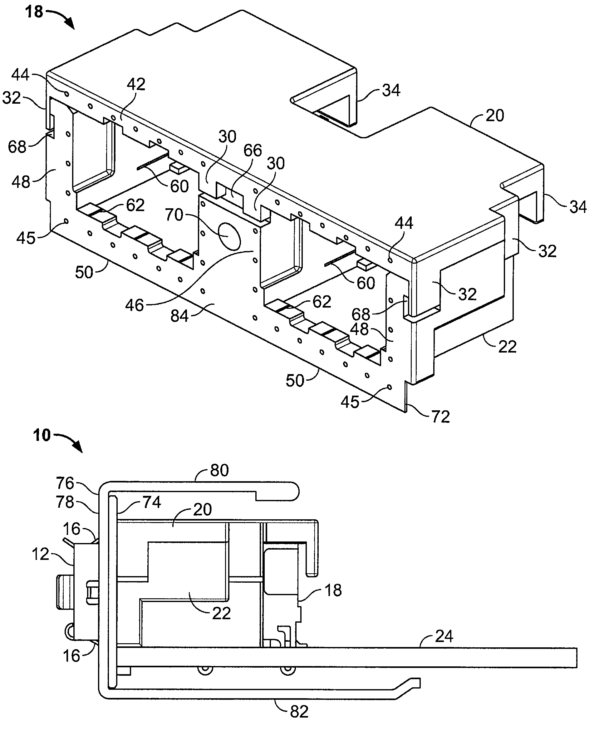
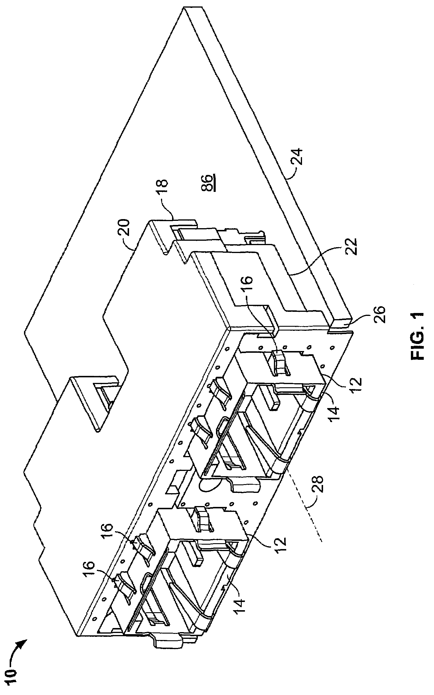
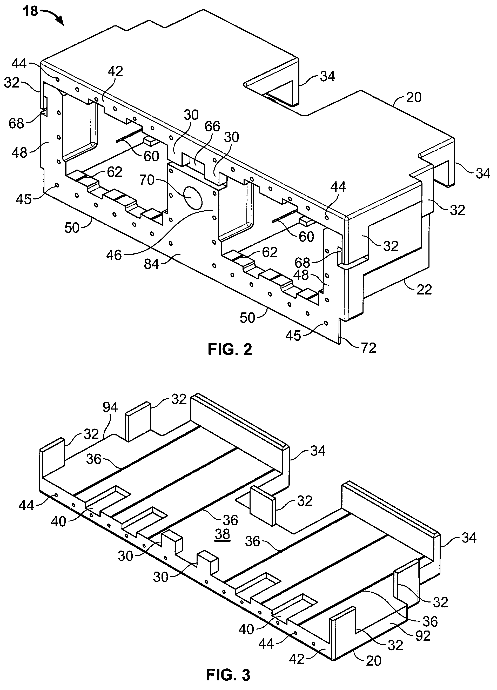
[0017]Referring to FIG. 1, an electrical connector assembly 10 according to the present invention includes a connector 12 having a housing 14 that is received by bracket portions 20, 22 of EMI bracket or bracket 18. As shown in FIG. 2, bracket portion 20 can also be referred to as an upper bracket portion 20 and bracket portion 22 can also be referred to as a lower bracket portion 22, although neither of terms upper and lower is intended to be limiting. In one embodiment, connector 12 is mounted on panel member 24, such as a printed circuit board, by a solder joint. However, other suitable techniques to secure connector 12 to panel member 24 may include fasteners, adhesives or locking constructions between connector 12 and panel member 24. As will be discussed in more detail below, bracket 18 is relatively movable along an axis 28 associated with connector 12 while maintaining electrical communication with connector 12, and without unduly stressing the affixed joint between connecto...


PUM

PropertyMeasurementUnit
frequencyaaaaaaaaaa
frequencyaaaaaaaaaa
electrical communicationaaaaaaaaaa

Abstract

A connector assembly configured for mounting on a panel member includes a connector having an axis. An EMI bracket surrounds the connector, the EMI bracket being relatively movable along the axis while maintaining electrical communication with the connector.

Description

FIELD OF THE INVENTION[0001]The present invention relates generally to electrical connector brackets and, more particularly, to electrical connector brackets for use with electrical panel members.BACKGROUND OF THE INVENTION[0002]Connectors are required to provide electrical power or electrical or electronic control signals between components, such as computers, printers, auxiliary hardware, etc. Often, these components contain panel members, such as printed circuit boards, which are populated with miniaturized components to provide the desired electrical control. Typically, the connector is affixed adjacent to one end of the panel member. A bezel is affixed to the panel member adjacent to the connector to minimize electromagnetic interference (EMI). EMI is defined as any electromagnetic radiation released by an electronic device that disrupts the operation or performance of another device. However, due to tolerance build-up during manufacturing associated with locating the connector...

Claims


Application Information

Patent Timeline
Patent Type & Authority Patents(United States)
IPC IPC(8): H01R13/648
CPCH01R13/658H01R13/659H01R13/6582Y10T29/49185Y10S439/939
Inventor BRIANT, ERIC DAVIDSHUEY, SCOTT ANTHONYFOGG, MICHAEL WARREN
Owner TE CONNECTIVITY CORP
Learn More