Monitor for auditory prosthesis

a monitor and auditory prosthesis technology, applied in the field of auditory prosthesis monitoring, can solve the problems of monitor failure to indicate malfunctions which may arise in the microphone, speech processor, transmitter coil, implanted stimulator/receiver unit, and often the inability of the implanted recipient to provide an accurate indication of whether the implant is operating correctly

Active Publication Date: 2007-05-29
COCHLEAR LIMITED
View PDF6 Cites 2 Cited by
  • Summary
  • Abstract
  • Description
  • Claims
  • Application Information

AI Technical Summary

Benefits of technology

[0029]In some embodiments of the method of the third aspect of the invention, the step of detecting may comprise placing a shield proximal to the transmitter, and monitoring a voltage of the shield induced by electromagnetic emissions of the transmitter. In such embodiments, the step of indicating may comprise passing the voltage of the shield to a transistor, such that the transistor is turned on when a voltage is induced in the shield. Preferably, such embodiments further comprise the steps of rectifying and low-pass filtering the voltage induced on the shield, in order to prevent the transistor changing state at the frequency of the signal transmitted by the transmitter.

Problems solved by technology

For instance, where the system is used on a person who has been profoundly deaf since birth, the implant recipient is often unable to provide an accurate indication of whether the implant is operating correctly.
Further, where the implant recipient is an infant, the infant is unable to provide any subjective indication of unsatisfactory or faulty operation.
Previous systems have monitored battery strength in the external processor unit, however such monitors fail to indicate malfunctions which may arise in the microphone, speech processor, transmitter coil, or implanted stimulator / receiver unit.
A further solution, set out in U.S. Pat. No. 5,941,905, has been to provide a guardian / teacher with a “wand”, comprising an antenna to detect emissions of a recipient's implant, However this arrangement necessitates individually checking each and every implant, which can be a particularly time consuming process where multiple implant recipients are present, and further complicates the already demanding task of teaching or nursing infants.
Further, with recent efforts to minimise electromagnetic interference caused by the RF link of such an implant, the performance of such “wands” may become less reliable, as minimal leakage fields may exist for the wand to detect.

Method used


Image

  • Monitor for auditory prosthesis
  • Monitor for auditory prosthesis
  • Monitor for auditory prosthesis

Examples


Embodiment Construction

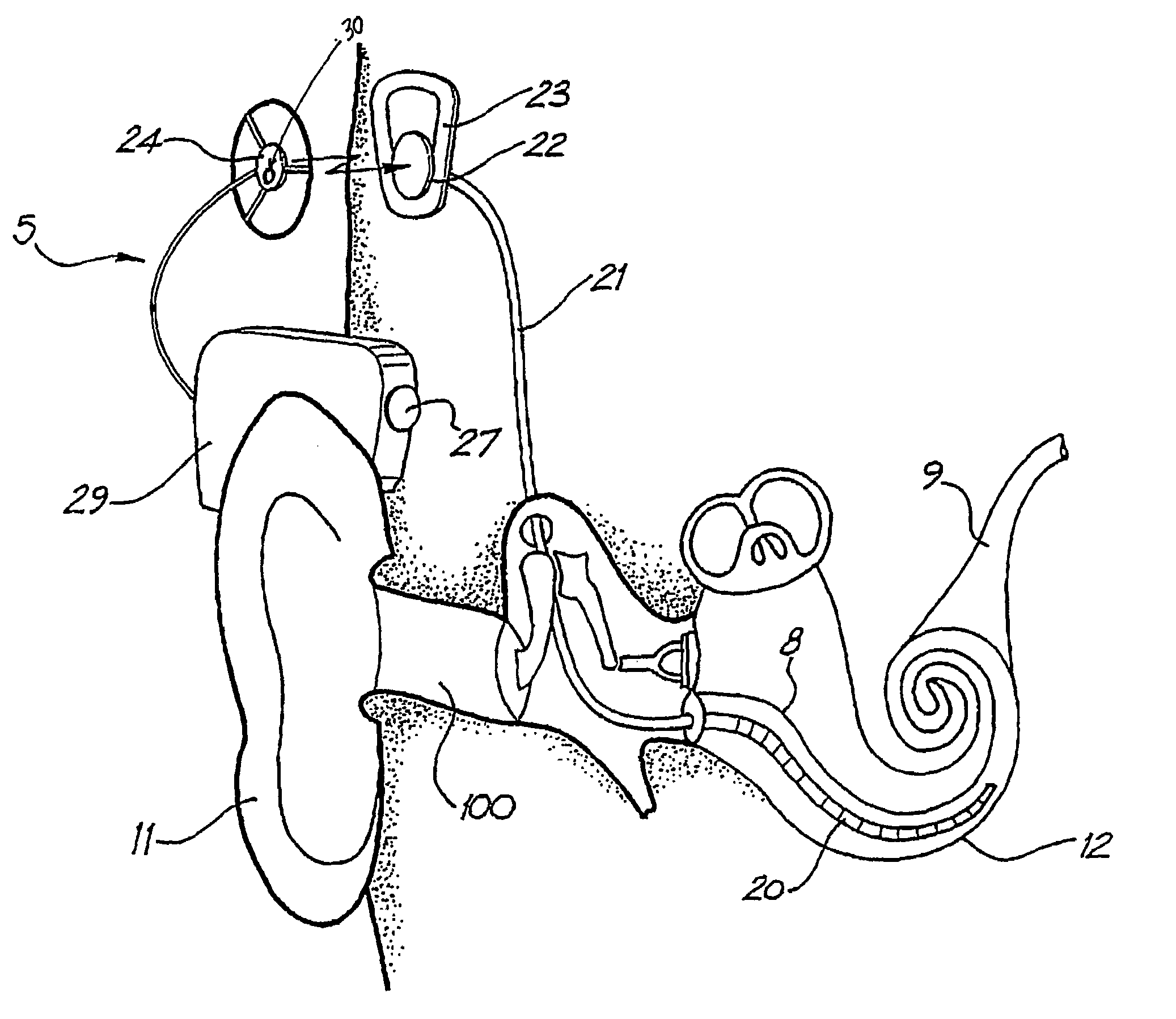
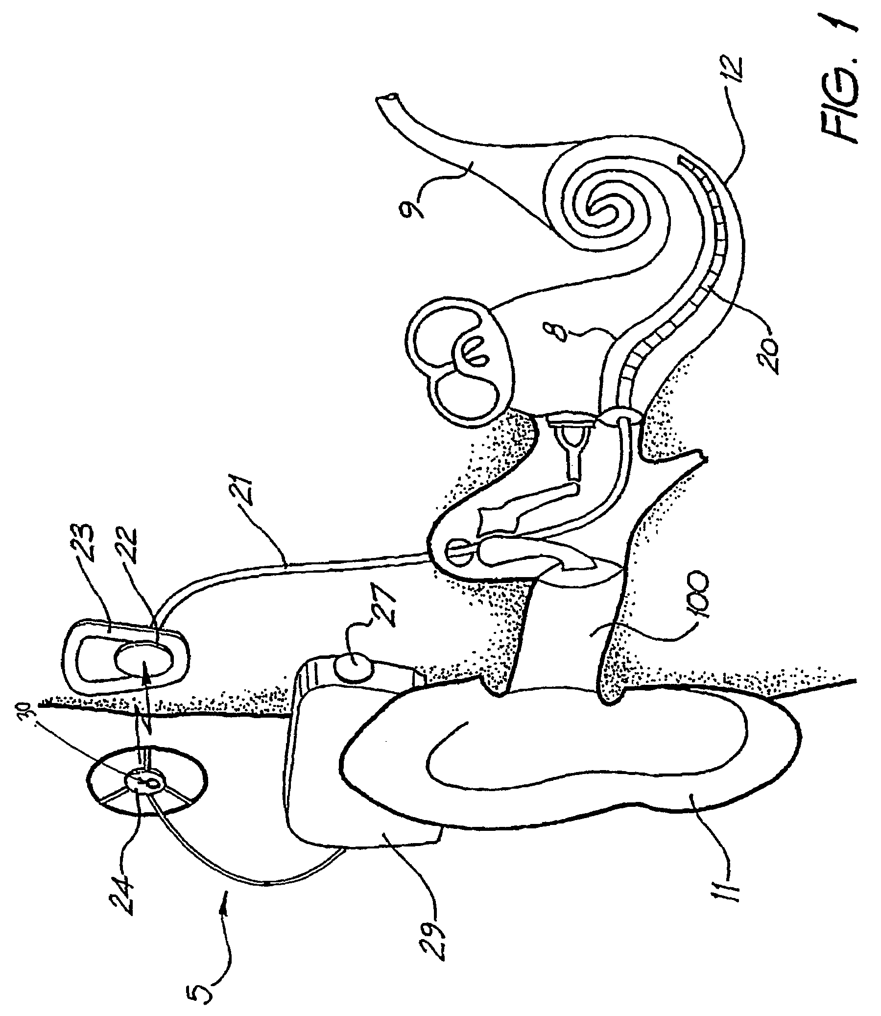
[0034]While the present invention is not directed solely to a cochlear implant, it is appropriate to briefly describe the construction of one type of known cochlear implant system with reference to FIG. 1.

[0035]Known cochlear implants typically consist of two main components, an external component including a speech processor 29, and an internal component including an implanted receiver and stimulator unit 22. The external component includes a microphone 27. The speech processor 29 is, in this illustration, constructed and arranged so that it can fit behind the outer ear 11. Alternative versions may be worn on the body. Attached to the speech processor 29 is a transmitter coil 24 that transmits electrical signals to the implanted unit 22 via a radio frequency (RF) link.

[0036]The implanted component includes a receiver coil 23 for receiving power and data from the transmitter coil 24. A cable 21 extends from the implanted receiver and stimulator unit 22 to the cochlea 12 and terminat...


PUM


Abstract

An auditory prosthesis includes an implanted component and an external component. The external component includes a transmitter for transmitting electromagnetic signals to the implanted component; means for detecting electromagnetic emissions of the transmitter; and means for indicating when the electromagnetic emissions of the transmitter have been detected.

Description

CROSS-REFERENCE TO RELATED APPLICATION[0001]This application is a National Phase Patent Application of International Application Number PCT / AU02 / 00726, filed on Jun. 5, 2002, which claims priority of Australian Patent Application Number PR 5513, filed Jun. 6, 2001.TECHNICAL FIELD[0002]The present invention relates to a method and apparatus for monitoring the operation of an auditory prosthesis, and in particular for monitoring the operation of a transmitter of an auditory prosthesis.BACKGROUND ART[0003]Cochlear implant systems have been developed in order to deliver electrical stimulation directly to the auditory nerve. Such a stimulation bypasses hair cells of the cochlea, which may be damaged or missing in persons who are profoundly deaf, and allows the brain to perceive a sensation resembling the natural hearing sensation normally delivered to the auditory nerve. U.S. Pat. No. 4,532,930, the contents of which are incorporated herein by reference, provides a description of one typ...

Claims


Application Information

Patent Timeline
Patent Type & Authority Patents(United States)
IPC IPC(8): A61N1/20A61N1/08A61F11/00A61F2/02H04R25/00
CPCA61N1/08H04R25/558A61F2250/0001
Inventor IBRAHIM, IBRAHIM HANNA
Owner COCHLEAR LIMITED
Why Eureka
Try Eureka