
System for and method of analyzing printed board carrying chassis, printed board carrying chassis structure, program, and recording medium

a printed board and chassis technology, applied in the direction of printed circuit non-printed electric components association, electrical apparatus construction details, instruments, etc., can solve the problems of unnecessary radiation (electro-magnetic interference) from the chassis that carries printed boards thereon, and no emi predicting method has been established, so as to reduce unnecessary radiation

Inactive Publication Date: 2010-11-23
NEC CORP
View PDF4 Cites 1 Cited by
  • Summary
  • Abstract
  • Description
  • Claims
  • Application Information

AI Technical Summary

Benefits of technology

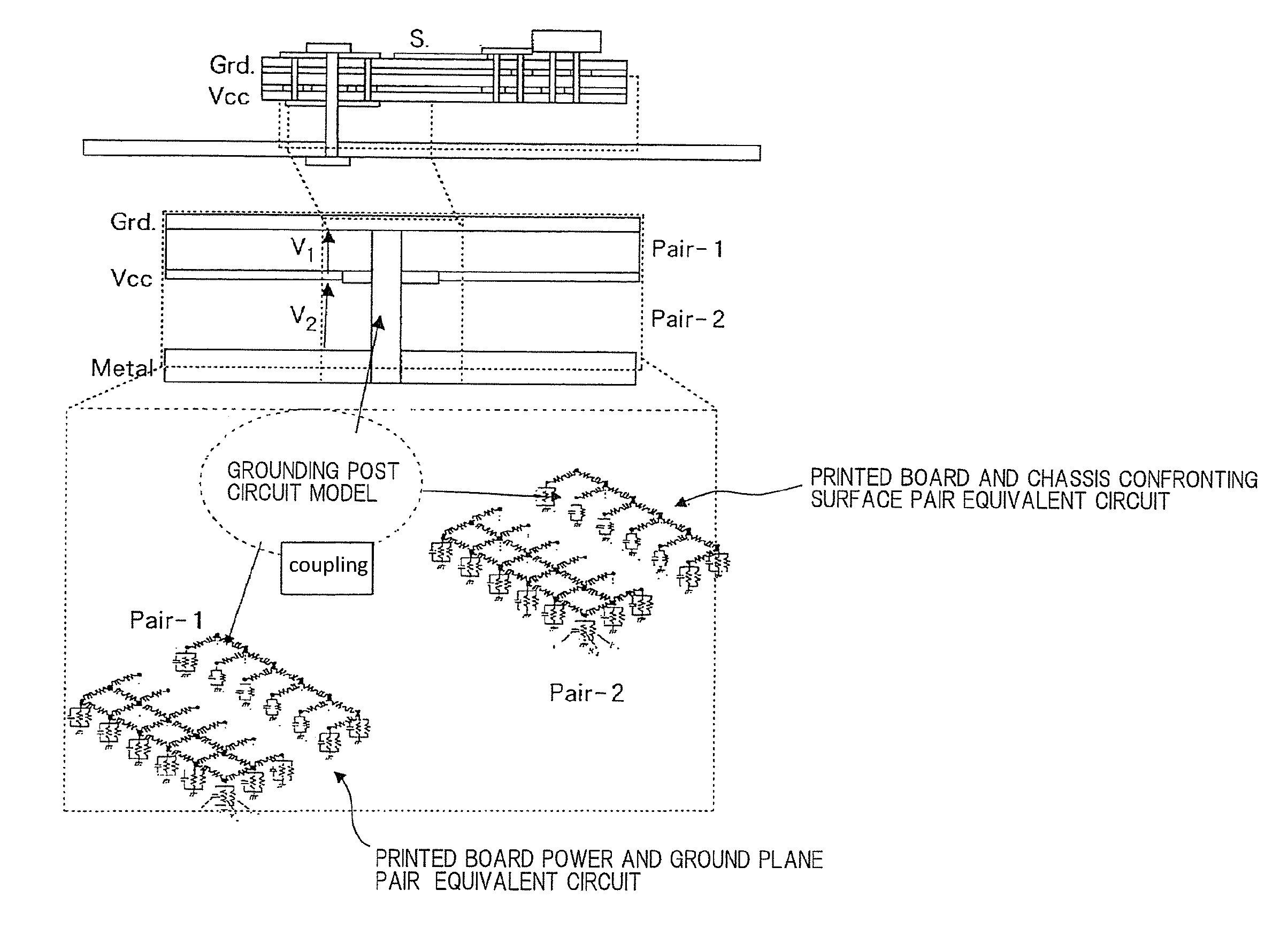
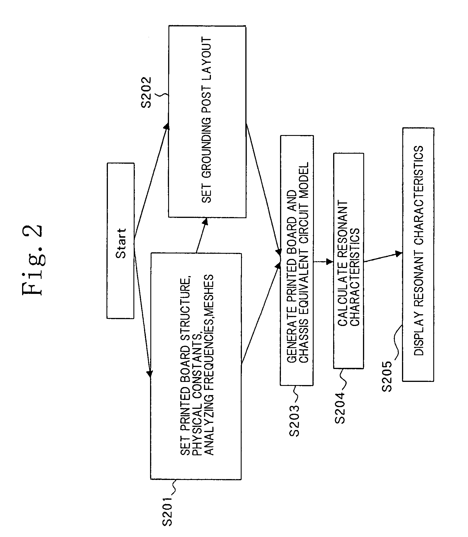
The present invention provides a method and system for analyzing the electromagnetic interference (EMI) in a printed board carrying chassis structure. The system can predict the frequency at which EMI increases and the impact of grounding posts on reducing EMI. The analysis is done by setting information about the printed board structure, physical constants, the positions of a noise source and an observation point, analyzing frequencies, and meshes. The system can also generate an equivalent circuit model and calculate the resonant characteristics of the printed board and the chassis using a circuit solver. The analysis results can be displayed and compared to identify the most significant EMI and suggest measures to reduce it. The invention is useful in designing and manufacturing printed board carrying chassis structures to minimize EMI and improve electrical performance.

Problems solved by technology

As electronic devices have become higher in speed, the problem of unnecessary radiation (hereinafter referred to as EMI (Electro-Magnetic Interference)) from the chassis that carries printed boards thereon has become more noticeable.
However, no EMI predicting method has been established yet for a structure in which a grounding post is connected between a printed board and a chassis.
The disclosed structure is, however, disadvantageous in that the mounting area is relatively small because the ground patterns need to be placed as the outer frames of the signal layers.
As described above, though the conventional chassis structure with the printed board mounted thereon can be analyzed for the prediction of the resonant frequency at which EMI is generated, if it has no grounding-posts, there is no method available to predict an EMI-generating resonant frequency for the conventional chassis structure if it has grounding posts.
The conventional structure in which ground patterns are placed as the outer frames of the signal layers and are connected to the grounding posts that are connected between the printed-wiring board ends and the chassis is problematic in that the mounting area of the printed-wiring board is limited by the ground patterns added as the outer frames of the signal layers.

Method used


Image

  • System for and method of analyzing printed board carrying chassis, printed board carrying chassis structure, program, and recording medium
  • System for and method of analyzing printed board carrying chassis, printed board carrying chassis structure, program, and recording medium
  • System for and method of analyzing printed board carrying chassis, printed board carrying chassis structure, program, and recording medium

Examples


first embodiment

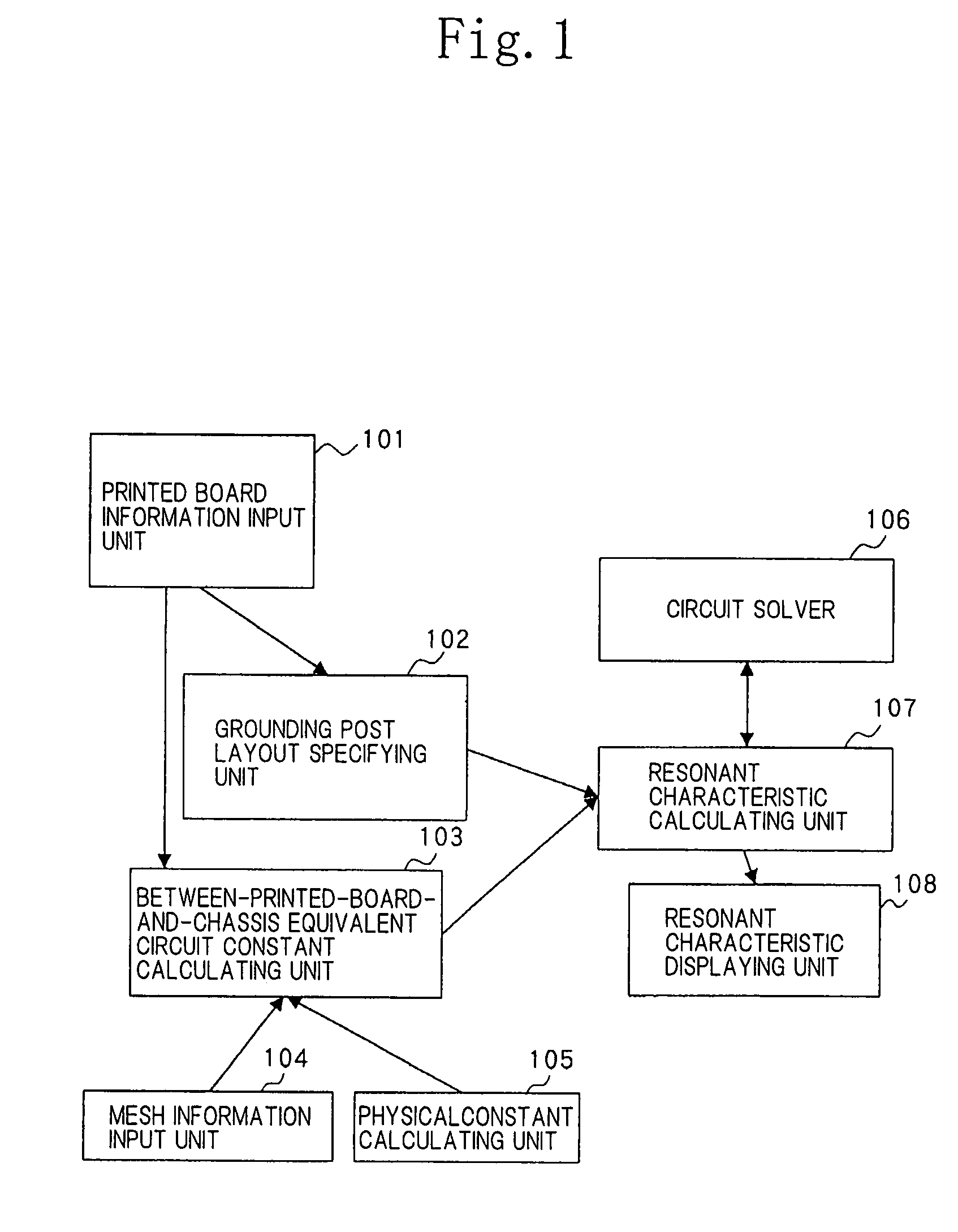
[0034]FIG. 1 shows in block form a printed board carrying chassis analyzing system according to the present invention.

[0035]As shown in FIG. 1, the printed board carrying chassis analyzing system according to the first embodiment of the present invention comprises printed board information input unit 101, grounding post layout specifying unit 102, between-printed-board-and-chassis equivalent circuit constant calculating unit 103, mesh information input unit 104, physical constant calculating unit 105, circuit solver 106, resonant characteristic calculating unit 107, and resonant characteristic displaying unit 108.

[0036]Printed board information input unit 101 is a unit for inputting structural information of a printed board to be mounted on a chassis. Specifically, printed board information input unit 101 has a function to input longitudinal and transverse dimensions, etc., of a printed board.

[0037]Grounding post layout specifying unit 102 has a function to specify the number, layou...

second embodiment

[0046]FIG. 3 shows in block form a printed board carrying chassis analyzing system according to the present invention.

[0047]As shown in FIG. 3, the printed board carrying chassis analyzing system according to the second embodiment of the present invention comprises printed board information input unit 301, grounding post layout specifying unit 302, printed board power supply system and chassis combination equivalent circuit constant calculating unit 303, mesh information input unit 304, physical constant calculating unit 305, printed board power supply system equivalent circuit calculating unit 306, printed board power supply system EMI evaluating unit 307, circuit solver 308, printed board power supply system and chassis combination equivalent circuit calculating unit 309, printed board power supply system and chassis combination EMI evaluating unit 310, and EMI comparing and displaying unit 311.

[0048]Printed board information input unit 301 is a unit for inputting structural infor...


PUM


Abstract

A structure has a printed board carried by a metal chassis. A printed board carrying chassis analyzing system, a printed board carrying chassis analyzing method, a printed board carrying chassis structure, and a printed board carrying chassis analyzing program are provided to achieve a screw-fastened arrangement for predicting unnecessary radiation frequencies and for reducing unnecessary radiation. An equivalent circuit model including a printed board power and ground plane pair, a pair of confronting surfaces of a printed board and a chassis, and screw-fastened grounding posts is generated and analyzed to predict unnecessary radiation frequencies and unnecessary radiation reductions and to select a screw-fastened arrangement for reducing unnecessary radiation.

Description

BACKGROUND OF THE INVENTION[0001]1. Field of the Invention[0002]The present invention relates to a structure in which a printed board is carried by a metal chassis, and more particularly to a printed board carrying chassis analyzing system, a printed board carrying chassis analyzing method, a printed board carrying chassis structure, and a printed board carrying chassis analyzing program for providing a screw-fastened arrangement which is effective to predict unnecessary radiation frequencies and reduce unnecessary radiation.[0003]2. Description of the Related Art[0004]As electronic devices have become higher in speed, the problem of unnecessary radiation (hereinafter referred to as EMI (Electro-Magnetic Interference)) from the chassis that carries printed boards thereon has become more noticeable. When a printed board is mounted on a chassis, it is the usual practice to electrically connect the ground plane of the printed board to the chassis with electrically conductive posts (her...

Claims


Application Information

Patent Timeline
Patent Type & Authority Patents(United States)
IPC IPC(8): G01R31/28
CPCG06F17/5036G06F30/367
Inventor KOBAYASHI, NAOKIMORISHITA, KENHARADA, TAKASHI
Owner NEC CORP
Learn More