Apparatus for extracting juice

a technology of apparatus and juice, applied in the direction of grain treatment, manufacturing tools, centrifuges, etc., can solve the problems of increasing power consumption, shortening the cycle life, increasing the amount of heat generated, etc., and achieve the effect of improving the efficiency of juice extraction and increasing the number of revolutions of driving means

Inactive Publication Date: 2012-09-13
SK MAGIC CO LTD
View PDF3 Cites 31 Cited by
  • Summary
  • Abstract
  • Description
  • Claims
  • Application Information

AI Technical Summary

Benefits of technology

[0017]Aspects of the present invention provide a juice extracting apparatus, which can improve juice extracting efficiency without increasing a number of revolutions of a driving means.
[0018]Aspects of the present invention also provide a juice extracting apparatus, which can easily clean components including an extracting net unit, while minimizing sludge stuck in or sticking on a component.
[0026]The cleaner may have interior grooves radially formed on its inner peripheral surface and the rotary extracting net unit may have exterior protrusions radially formed on its outer peripheral surface, so that the exterior protrusions of the rotary extracting net unit are accommodated in the interior grooves of the cleaner, thereby guiding rotation of the cleaner.
[0033]As described above, in the juice extracting apparatus according to the present invention, an extracting screw unit rotates in a first direction and a rotary extracting net unit rotates in a second direction opposite to the first direction in which the extracting screw unit rotates, thereby improving juice extracting efficiency even with a small driving force (a rotational force).
[0034]In addition, since the extracting screw unit and the rotary extracting net unit rotate in opposite directions, sludge existing between the extracting screw unit and the rotary extracting net unit can be minimized and effectively cleaning the outer peripheral surface of the rotary extracting net unit.

Problems solved by technology

In this case, load may be applied to a driving means, thereby shortening a cycle life, increasing the amount of heat generated and increasing power consumption.
In addition, if a rotational speed of the driving means increases to exceed a predetermined range, nutrients of juice may be destructed, so that there is a limit in increasing the number of revolutions.
In the horizontal or vertical type juice extracting apparatus having an extracting net unit fixedly installed, when protrusions or grooves are soiled with sludge, it is quite difficult to perfectly wash the juice extracting apparatus.

Method used


Image

  • Apparatus for extracting juice
  • Apparatus for extracting juice
  • Apparatus for extracting juice

Examples


first embodiment

[0060]Hereinafter a juice extracting apparatus according to the present invention will be described.

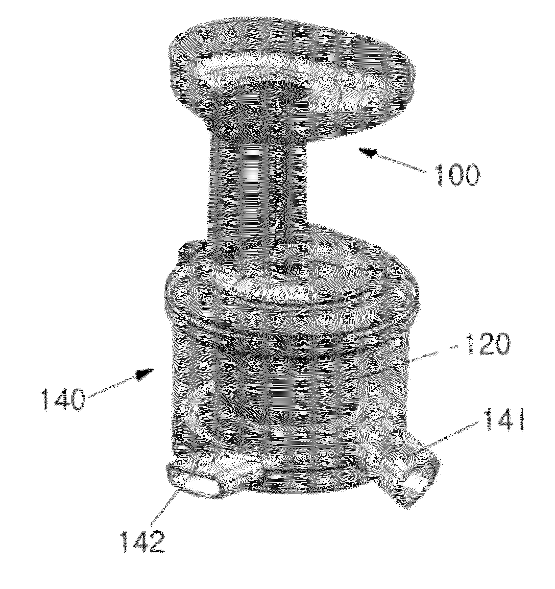
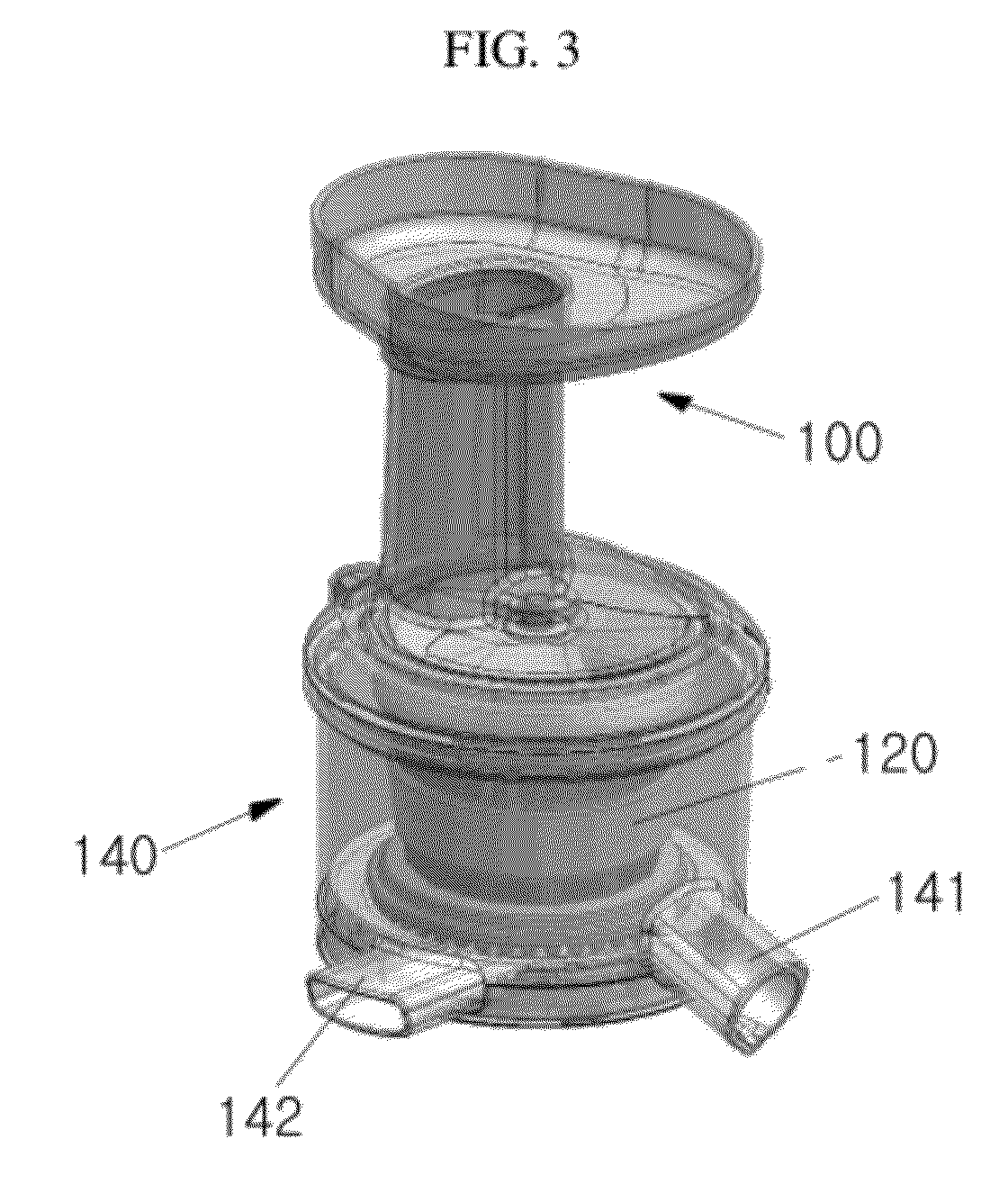
[0061]As shown in FIGS. 3 to 5, the juice extracting apparatus according to the first embodiment of the present invention includes an injection cover 100, an extracting screw unit 110, a rotary extracting net unit 120, a discharge guide unit 130 and an extracting case 140.

[0062]First, the injection cover 100 includes a hopper-shaped inlet 101 formed at its top portion to inject a material for extracting juice, such as fruits or vegetables (hereinafter, referred to as “raw material”); an injection pipe 102 integrally formed with the inlet 101 at a lower portion of the inlet 101 so that the injected raw material is vertically conveyed, and a plurality of engagement protrusions 103 radially formed at a bottom portion of the injection cover 100 to be engaged with the extracting case 140.

[0063]The extracting screw unit 110 includes a screw shaft 113 (shown in FIG. 6) having an insertion pr...

second embodiment

[0093]Hereinafter, the operation of the juice extracting apparatus according to the present invention will be described with reference to the following drawings.

[0094]As shown in FIG. 15, if a raw material is injected into the inlet 201, the extracting screw unit 210 engaged with the drive shaft 251 of the driving means, thereby slicing the raw material by the screw blade 211. In addition, the raw material is pulverized and conveyed by a guide protrusion 221 of the rotary extracting net unit 220 rotating in the opposite direction to a direction in which the extracting screw unit 210 rotates.

[0095]Like in the first embodiment of the present invention, the sun gear 212 of the extracting screw unit 210, the plurality of planet gears 231 of the discharge guide unit 230 and the ring gear 223 of the rotary extracting net unit 220 are engaged with each other. Accordingly, as the extracting screw unit 210 rotates, the rotary extracting net unit 220 rotates in the opposite direction to the d...

third embodiment

[0101]FIG. 16 illustrates an interior side of an extracting case 240 of an according to the present invention, FIG. 17 is a perspective view of a cleaner 300 shown in FIG. 16, and FIG. 18 is a cross-sectional view of a juice extracting apparatus with cleaner 300 shown in FIGS. 16 and 17. Here, a driving means is illustrated in the above drawings.

[0102]The general configuration of the juice extracting apparatus according to the third embodiment of the present invention is substantially the same as that of the juice extracting apparatus according to the second embodiment of the present invention. Therefore, the following description will focus on different structures in both embodiments. In addition, in the following embodiment, components having substantially the same function as the second embodiment are identified by the same reference numerals, and detailed descriptions thereof will be omitted.

[0103]The juice extracting apparatus according to the third embodiment of the present in...


PUM


Abstract

A juice extracting apparatus, which can improve juice extracting efficiency without increasing a number of revolutions of a driving means, is disclosed. A juice extracting apparatus, which can easily clean components including an extracting net unit, while minimizing sludge stuck in or sticking on a component, is also disclosed.

Description

CROSS-REFERENCE TO RELATED APPLICATION[0001]This application claims priority of Korean Patent Application No. 10-2011-0019958, filed on Mar. 7, 2011 and priority of Korean Patent Application No. 10-2011-0071359, filed on Jul. 19, 2011, in the KIPO (Korean Intellectual Property Office), the disclosure of which is incorporated herein entirely by reference.BACKGROUND OF THE INVENTION[0002]1. Field of the Invention[0003]The present invention relates to an apparatus for extracting juice type food by squeezing fruits, vegetables or beans.[0004]2. Description of the Related Art[0005]A juice extracting apparatus is an apparatus for extracting juice by squeezing agricultural and marine products such as fruits, vegetables or beans.[0006]The configuration and functions of a conventional juice extracting apparatus are as follows.[0007]FIG. 1 is a schematic drawing showing a conventional horizontal type juice extracting apparatus.[0008]As shown in FIG. 1, in the horizontal type juice extracting ...

Claims


Application Information

Patent Timeline
Patent Type & Authority Applications(United States)
IPC IPC(8): A23N1/00B02C25/00
CPCA47J19/025A47J19/02
Inventor LIM, TAE GYULEE, CHUL GULEE, KYOUNG HOKANG, DONG HOON
Owner SK MAGIC CO LTD
Why Eureka
Try Eureka